Heath Zenith Wireless Outdoor Power Control 6022 User Manual
Wireless outdoor power control, Model 6022, Operation
ON DIP
1 2 3 4
ON DIP
1 2 3 4
© 2007 HeathCo LLC
598-1236-01
Wireless Outdoor Power Control
Model 6022
Operation
Eight selectable channels allow the user to operate several sys-
tems at different locations in your home. If purchasing more than
one wireless control system, select different operating channels
for each system or they will interact with each other.
1. Remove Tab from Battery Chamber. Remove cover from
back of transmitter by pressing on it with your thumb and
sliding it off as shown in Figure 1. Gently pull tab out of bat-
tery chamber. Slide cover onto transmitter.
2. Check operation. Place hand over light sensor cover. The
unit should switch on. To check remote operation, toggle left
switch to manual. Toggle ON/OFF switch.
3. Remote Control Functions.
Automatic Mode: Toggle left switch to automatic to allow
switched devices to come on at dusk and turn off at dawn.
This is the default mode when fi rst powered up or after power
outage.
Manual Mode: Toggle left switch to manual to allow operator
to manually switch devices on and off. Use right toggle to
switch devices on and off.
Note: LED will light when toggle switches are pushed.
Manual
Switch
Auto
Switch
ON Switch
OFF Switch
LED Indicator Light
Remote Control
12-Volt (A23 Type)
Battery (Included)
Clip
Figure 1
Battery
Chamber
(Type A23)
Battery
Cover
Tab
Positive Terminal
Channel Settings
Note: Most installations will not require you to change
any of the dip switches on your plug-in module or remote
control.
The remote control and outdoor module communicate by using
channels that can be changed by sliding dip switches into the
ON or OFF [on some switches the numbers 1 (ON) and/or 0
(OFF) are used] position on both the remote control and outdoor
module. The channel is factory set; however, there are 3 switches
(8 selectable channels) that allow you to expand your system
and prevent outside interference. Other wireless products may
cause interference and the system may not function properly.
Follow the instructions below for setting a new channel.
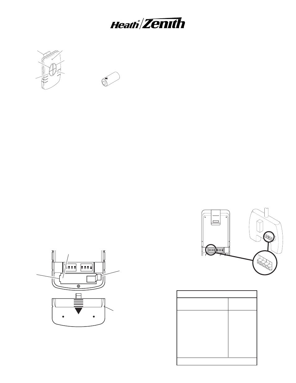
1. Open the cases and locate dip switches on both the remote
control and outdoor module (see Figure 2).
2. The remote control and outdoor module both have two
positions (ON and OFF) on each of the four dip switches.
Dip switches 1 through 3 are used for setting the channel.
Use the table below to set channel 2 after setting channel
1. Note: The channels must be programmed according to
the table below for all 4 functions of the remote control to
work properly. The receiver(s) must match the code settings
for channel 1. Use the table below to set the corresponding
code for channel 2.
3. To change the channel, slide dip switches to ON or OFF as
needed. It is recommended to only change one dip switch
at a time and then check to see if the system is functioning
properly. Note: Dip
switches in posi-
tions 1 through
3 must be in the
exact same con-
fi guration on both
the remote con-
trol and outdoor
module for this
system to function
properly.
ON
1 2 3 4
Dip Switches - Shown
in the OFF Position
(Factory Default)
ON DIP
1 2 3 4
ON DIP
1 2 3 4
Figure 2
ON
1 2 3 4
Channel Setting Codes
Channel 1 Transmitter Channel 2
and
Receiver(s) Transmitter
0000
0001
0010
0011
0100
0101
0110
0111
1000
1001
1010
1011
1100
1101
1110
1111
0 = OFF
1 = ON