Installation – Holland XL-AR452 User Manual
Page 4
4
XL-AR452 Rev. C
INSTALLATION
continued
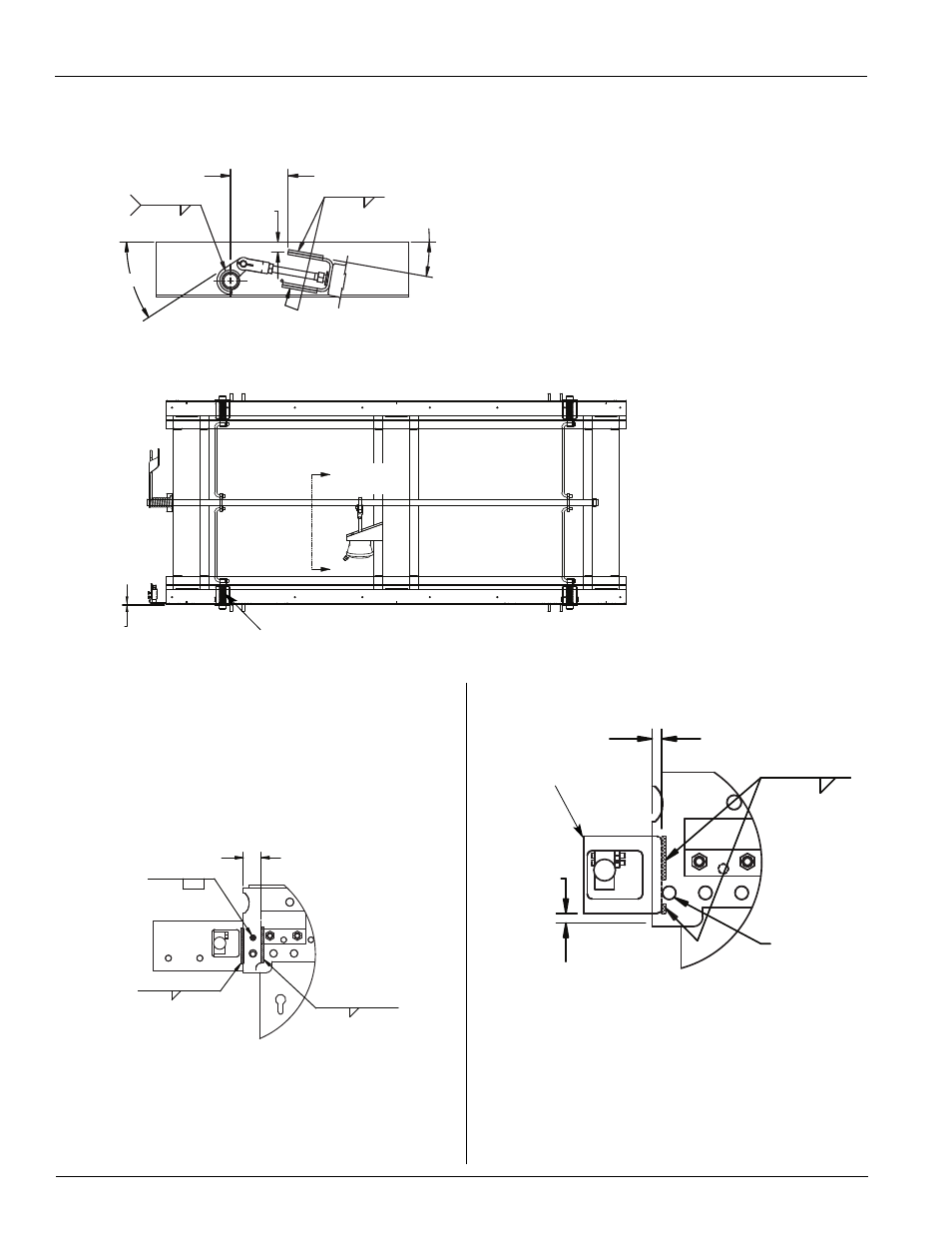
FIGURE 4A
Welding Actuator Chamber Cam Bracket (Mechanical Suspension)
0.16˝
FIGURE 4
Welding Actuator Chamber Cam Bracket (Mechanical Suspension)
10°
0.77˝
0.19˝
33°
4.49˝
0.19˝
BOTH
SIDES
MIDDLE CROSSMEMBER
COMPRESSION SPRING
4.
For the Mechanical Suspension notice the Actuator
Chamber Bracket is at an angle and the Spring Brake Cam is
located with the cam pin location on the top of the
Torsion Cam Tube.
5.
Locate the Valve Bracket as shown in
FIGURE 5
and
FIGURE 6
.
NOTE: For air release without stinger mounting bracket.
6.
Install the Actuator Chamber and male connector.Torque all
air chamber 1/2˝, mounting bracket nuts to 50 - 60 ft. lbs.
7.
Install the Air Release Control Valve. Refer to the Air Release
Plumbing Diagram for proper plumbing (
FIGURE 7
).
FIGURE 5
Locating Valve Bracket
FIGURE 6
Locating Valve Bracket
0.19˝
MOUNTING
BRACKET
0.25˝
1.63˝ +0.00 -0.06˝
HOLE MUST BE
FREE OF WELD
SPATTER
0.50˝ +0.00˝ -0.06˝
0.25˝
0.25˝
3.25˝
0.50˝ ±0.06˝
NOTE:
For air release with stinger mounting bracket.
3.25˝
SEE
FIGURE 4