D-sub connector pin assignments, Figure 14, D-sub connector pins – Honeywell HMLCD17e2 User Manual
Page 20: Table 1, D-sub pin settings
20
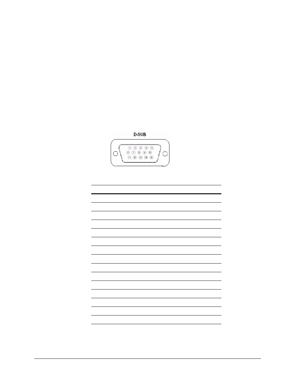
D-Sub Connector Pin Assignments
D-Sub Connector Pin Assignments
Figure 14 D-Sub connector pins
Table 1
D-SUB Pin Settings
Pin
Description
1
Red Video
2
Green Video
3
Blue Video
4
Ground
5
Ground
6
Red Ground
7
Green Ground
8
Blue Ground
9
10
Signal Cable Detect
11
Ground
12
SDA (for DDC)
13
H-SYNC (or H+V SYNC)
14
V-SYNC
15
SCL (for DDC)
This manual is related to the following products: