Harbor Freight Tools 96462 User Manual
Page 6
Page 6
SKU 96462
For technical questions, please call 1-800-444-3353.
Note:
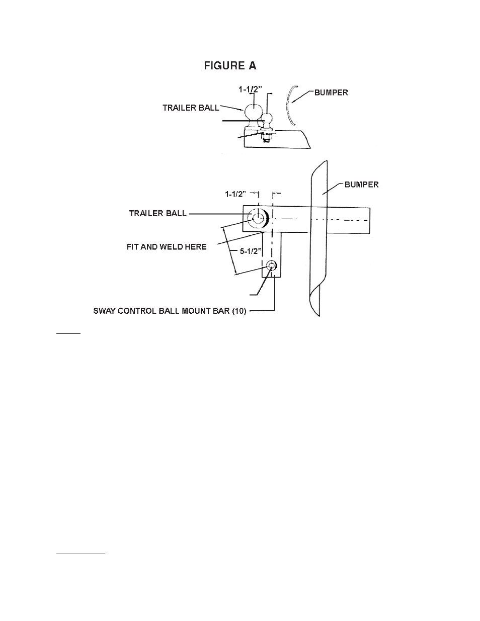
SWAY CONTROL BALL (13)
SWAY CONTROL BALL (13)
Most weight distributing ball mounts come equipped with a sway control ball
plate attached. If so, attach the Sway Control Ball (13) to the vehicle’s ball mount
using the hole provided. If no sway control ball hole is provided, weld the Sway
Control Ball Mount Bar (10) to the vehicle’s ball mount.
(See Figure A and Assy. diagram page 10)
Measure 24” straight back from the center of the coupler to the right hand side of
the trailer frame to determine the location of the Mounting Plate (1). The Trailer
Tongue Ball (3) must be centered on the 24” measurement.
NOTE: If installment
on the left side of the trailer is desired, measure 24” straight back from the center
of the coupler to the left hand side of the trailer frame to determine the location of
the Mounting Plate (1).
(See Figure B and C on page 7, and Assy. diagram)
Use the mounting holes in the Mounting Plate (1) as a template with which to drill
eight 11/32” diameter holes in the trailer frame.
If the marked holes cannot be drilled properly, then the Trailer Tongue Ball
must be welded directly onto the side of the trailer.
Otherwise, attach the Mounting Plate (1) and Trailer Tongue Ball (3) to the
trailer frame, using the eight self-tapping Screws (2) provided.
WARNING!
Make sure all welds are strong and capable of holding the tension placed
on them by the Sway Control unit before going on to the next step.
1.
2.
a.
b.