Tn2 standard system design options, Mechanical or electronic meter/turbine options, 3200nxt electronic controller – Hellenbrand TN2 Series User Manual
Page 3: 3214nxt demand flow network controller
TN2 Standard System Design Options
(for more specific information on the various system designs, contact your local Hellenbrand representative or go to: www.hellenbrand.com
Mechanical or Electronic Meter/Turbine Options:
Size
Flow Ranges
Accuracy
1.5” CC Meter 0.5 – 60 GPM
+5%
2” CC Meter
1.5 - 150 GPM
+5%
1. Single Tank Systems - XT Controller
• Time Clock
• XT Controller Electronic Meter Demand
2. Twin, Tri-Plex & Four-Plex Systems - 3200NXT Controller
Parallel Operation
• 2-4 Units
• Individual Meters
• Single or Individual Brine Systems
Alternating Operation
• 2-4 Units
• Twin Systems - One Meter or Two Meters
• Tri-Plex & Four-Plex Systems - Individual Meters
• Single or Individual Brine Systems
The 3200NXT Network Controller uses on-board communica-
tions capabilities to link multiple valves (via off-the shelf CAT3,
CAT5, or better cables) for a variety of multiple system types as
described above.
Program Features:
• 2x16 character backlit LCD display
• Networks up to four units
• Auxiliary inputs and outputs
- Remote signal start input
- Remote lockout input
- Programmable relay output/chemical pump output
• Easy installation with plug-in wiring harnesses
• Front panel diagnostics button
- Flow rate
- Peak flow rate
- Totalizer
- Hours between last two regenerations.
- Hours since last regeneration
- Adjustable volume remaining
- Valve position
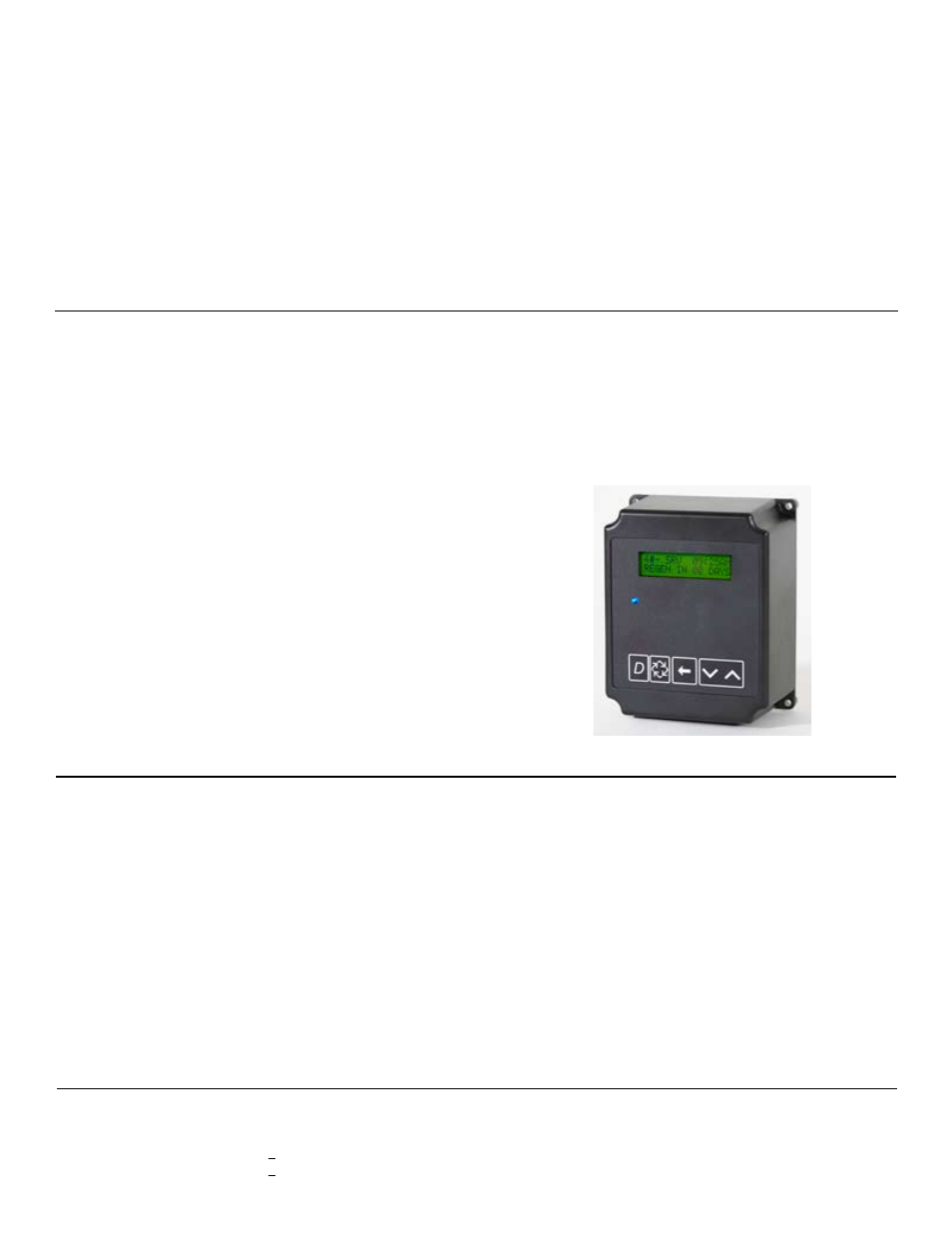
3200NXT Electronic Controller
3. Twin, Tri-Plex & Four-Plex Demand Recall Progressive
Systems - 3214NXT Controller
• 2-4 Units
• Individual Meters
• Single or Individual Brine Systems
Three programming levels
• User mode
• Master programming
• Diagnostics mode
Note: The 3214NXT Demand Flow Network Controller is used
for demand recall applications.
3214NXT Demand Flow Network Controller
The 3214NXT Demand Flow Network Controller can be pro-
grammed to bring multiple units to the service position and back
to standby based on system demand flow. The 3214NXZT De-
mand Flow Network Controller used on-board communication
capabilities to link multiple valves via standard CAT3, CAT5, or
better communication cables.
Program Features:
• Network two to four valves
• Simple, on-site network programming
• Easy installation with plug-in wiring harnesses
• Shift key allows digit selecting in programming
• 2x16 character LCD backlit display
(letter or digit codes not needed)
• Valve, piston, and cam type default storage
• User and master programming modes
• Diagnostic mode:
- Current flow rate
- Peak flow rate (can be reset)
- Totalizer (can be reset)
- Hours between last two regenerations
- Hours since last regeneration
- Volume remaining (adjustable)
- Valve addresses
Three programming levels
• User mode
• Master programming
• Diagnostics mode