Installation – Hotpoint GF641 User Manual
Page 8
8
Installation
The following instructions are intended for the installer so that the
installation and maintenance procedures may be followed in the
most professional and expert manner possible. Important:
Disconnect the appliance from the electrical supply before
performing any maintenance or repair.
Positioning the Hob
Important: this unit may be installed and used only in
permanently ventilated rooms in accordance with British
Standard Codes Of Practice: B.S. 6172 / B.S. 5440, Par. 2 and
B.S. 6891 Current Editions. The following requirements must be
observed:
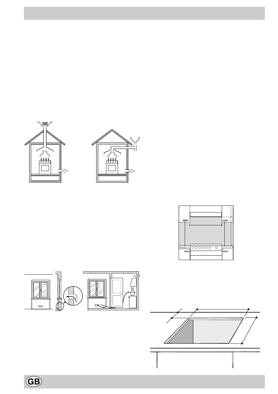
a) The room must be fitted with a ventilation system which vents
smoke and gases from combustion to the outside. This must
be done by means of a hood or electric ventilator that turns
on automatically each time the hob is operated.
In a chimney stack or branched flue.
Directly to the Outside
(exclusively for cooking appliances)
b) The room must have an air flow to allow for proper combustion.
This must be 2 m
3
³/h per kW of installed power. The airflow can
be created using an enclosed vent with an inner cross section
of at least 100 cm² which must not be able to be blocked. I the
appliance does not have a flame failure device, the vent must
have an internal cross section of 200 cm
3
³ (Fig. A). Alternatively
the room in which the hob is situated can be vented indirectly
through ventilation ducts as specified above, as long as the
adjacent room is not a shared area, a bedroom or present any
risk of fire (Fig. B).
Detail A
Adjacent
Room to be
Room
Vented
A
Examples of ventilation holes
Enlarging the ventilation slot
for comburant air.
between window and floor.
Fig. A
Fig. B
c) Intensive and prolonged use of the appliance may necessitate
supplemental ventilation, e.g. opening a window or increasing
the power of the air intake system (if present).
d) Liquidified petroleum gases are heavier than air and, as a result,
settle downwards. Rooms in which LPG tanks are installed
must be fitted with ventilation openings to the outside in order to
allow the gas to escape in the event of a leak. Therefore, LPG
tanks, whether empty or partially full, must not be installed or
stored in rooms or spaces below ground level (cellars, ect.). It is
also a good idea to keep only the tank currently being used in
the room, making sure that it is not near sources of heat (ovens,
fireplaces, stoves, etc.) that could raise the internal temperature
of the tank above 50°C.
Installation of Built-in Hobs
The gas hob is equipped with type X degree protection against
overheating. Therefore, the appliance can be installed next to
cabinets, provided the height of the cabinet does not exceed that of
the hob. For proper installation of the hob, the following guidlines
must be followed:
a) If the cabinet(s) located next to the hob are higher than the hob
itself, the cabinet(s) must be installed at least 110 mm from the
hob edge.
b) Hoods must be installed in accordance with the instructions
contained in the installation manual for the hoods themselves,
and no less than 650 mm from the hob.
c) In the case of the 600 mm cooker hoods, besides following
the recommendations in point b), the cabinets should be
positioned next to the hood at a height of at least 540 mm
from the top since this will make it possible to install the lid
and move it correctly. The cabinet should always be installed
at a height from the top which allows easy use of pots and
pans on the cooker.
d) Should the hob be installed directly under a cupboard, the latter
should be at least 700 mm (millimetres) from the top, as shown
in Figure C.
Fig. C
e) The dimensions of the cutout for the appliance must be those
indicated in the figure D. Clamps are provided to fasten the hob
to counters measuring from 20 to 40 mm in thickness. To fasten
the hob securely, it is recommended that all the clamps be
used.
Fig. D
HOOD
420
Min.
min.
650
mm. with hood
min.
700
mm. without hood
mm.
600
Min.
mm.
420
Min.
mm.
555 mm.
55 mm.
475 mm.