Warning – Exmark Mhp4816bv User Manual
Page 32
- 27 -
e)
Lower Sheave retaining bolt on clutch arm.
Adhesives such as “Loctite RC/609 or RC/680”or“Fel-Pro Pro-Lock Retaining I
or Retaining II” are used on the following:
a)
OPC lever hubs and cross-shaft
NOTE:
Care must be used not to bond the bearing, next to each OPC
hub, to the cross shaft which could cause binding of the OPC levers and
erratic operation.
5.1.19 An anti-seize compound is used on the following locations:
a) Between engine crankshaft and transmission and blade drive sheaves.
b) On clutch arm assembly between bearings and shaft and between lower
sheave and shaft.
c) Between transmission shaft and sheaves.
d) Between the cutter housing spindles and sheaves.
5.1.20 Dielectric grease is used on all blade type electrical connections to prevent
corrosion and loss of contact.
5.2 ADJUSTMENTS
5.2.1
Cutting height and anti-scalp roller adjustment.
WARNING
POTENTIAL HAZARD
♦
When the two front support rod hairpins are removed
from the mower deck, the weight of the tractor section
may cause the front frame to rise suddenly
WHAT CAN HAPPEN
♦
If the unit rises suddenly, injury may occur.
HOW TO AVOID THE HAZARD
♦
Securely hold down the front of the unit when the front
support rod hairpins are removed.
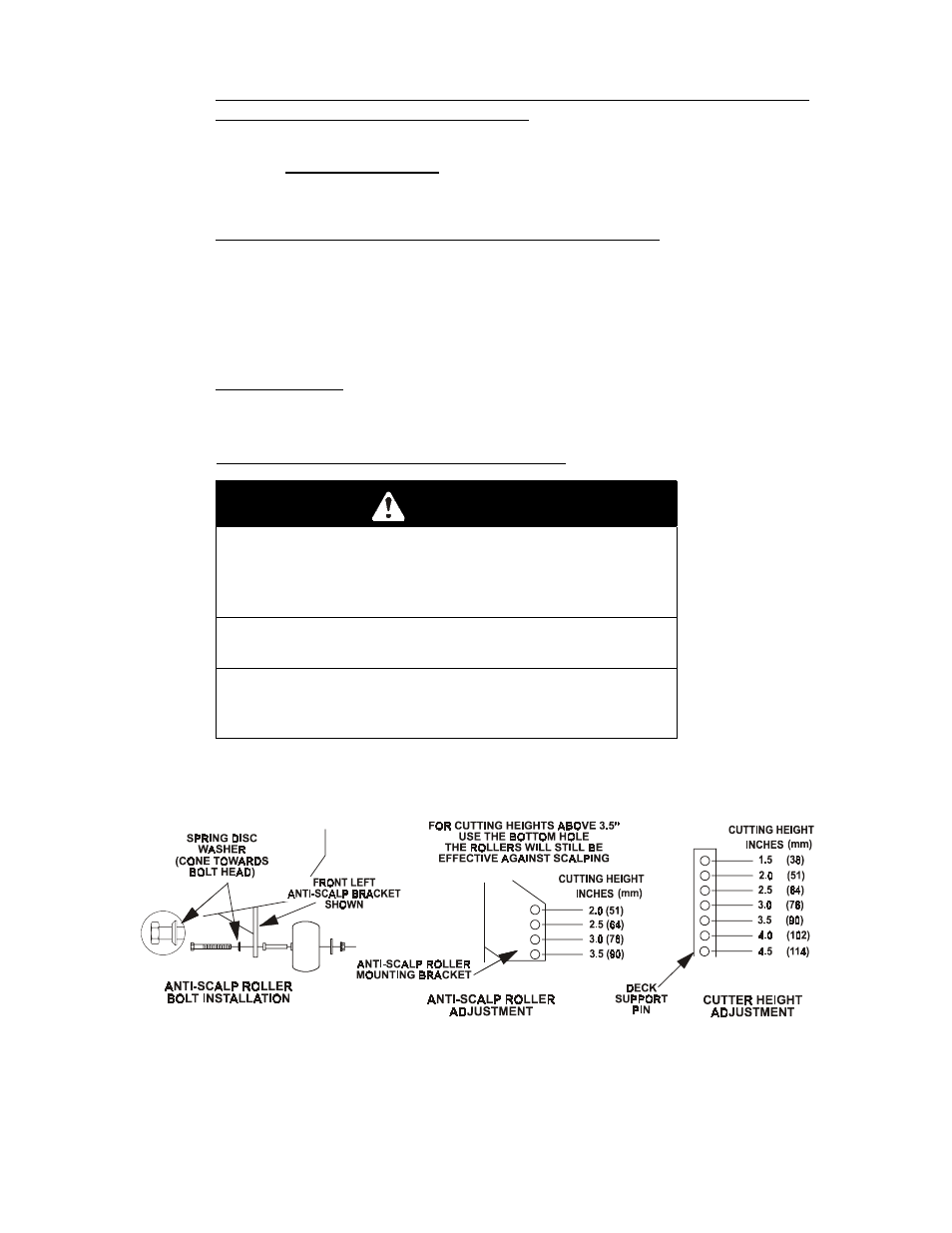
a)
Install hairpin clips in the holes shown on sketch below for the desired
cutting height (See Figure 14).
FIG 14
ANTI-SCALP ROLLER BOLT INSTALLATION
ANTI-SCALP ROLLER AND CUTTING HEIGHT ADJUSTMENT
b) Adjust anti-scalp rollers for Normal Operating Conditions. Stop engine.
Place rollers in one of the positions shown in Fig 14. Rollers will maintain
3/4 in. (19 mm) clearance to the ground to minimize gouging and roller
wear or damage. For Maximum Deck Flotation, place rollers one hole
position lower. Rollers should maintain 1/4 in. (6.4 mm) minimum