Troubleshooting - humidity signal verification, 4 to 20 ma signal – Emerson SL-31080 User Manual
Page 3
SL-31080 Product Specification/Installation Sheet
page 3
6/03 (Rev. 0)
Troubleshooting - Humidity Signal Verification
4 to 20 mA Signal
You will measure the humidity output by placing an ammeter in series with the controller input. The control-
ler input is connected to the terminal marked “Ch1 or Ch2” on the humidity board.
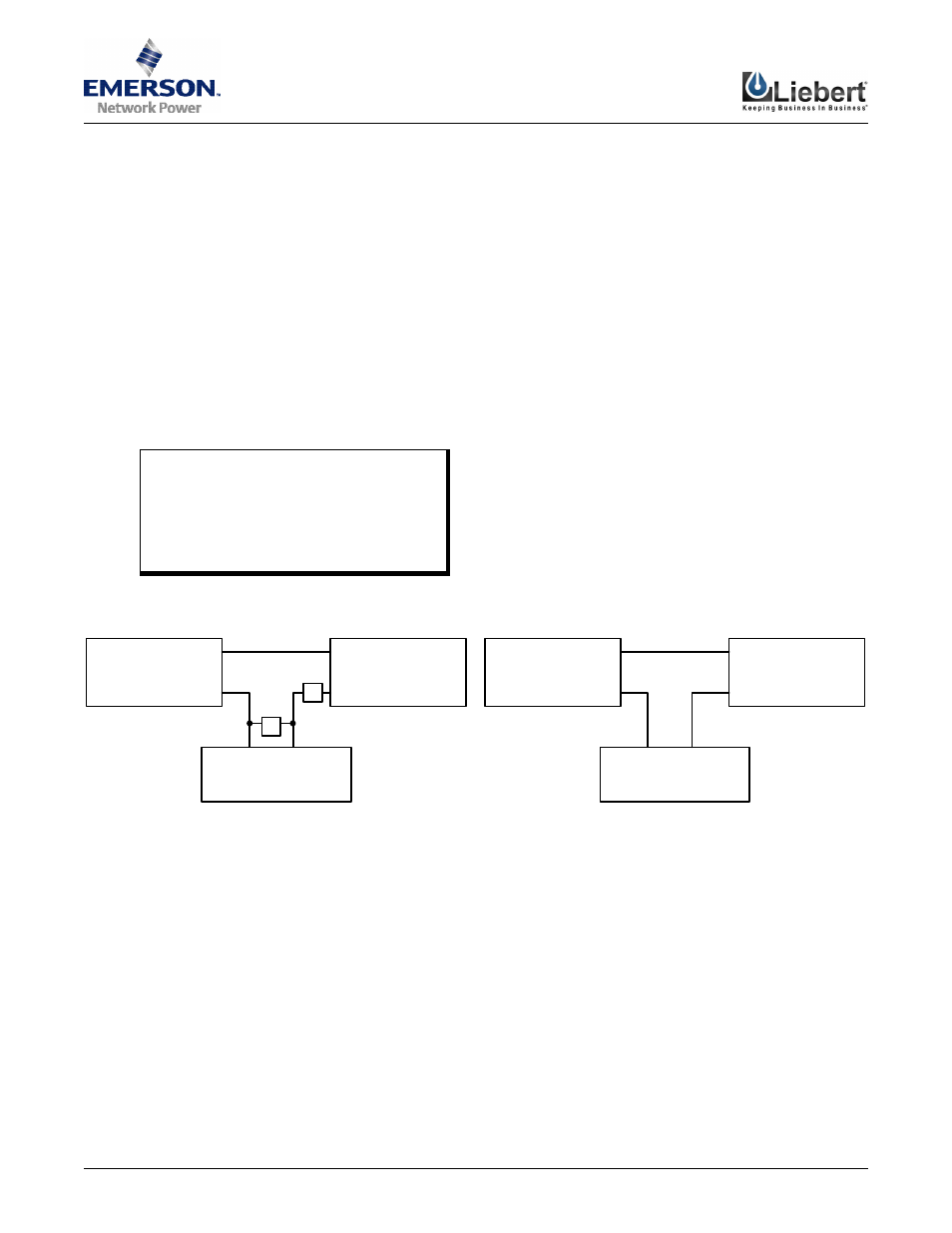
1. Verify the unit is terminated properly using Figure 2 shown below, and set your meter to the “Volts”
setting.
2. Verify you have 24 VDC supplied to the unit by measuring between the “V+” and “GND” terminals at the
sensor, as shown below in Figure 1.
3. Set your meter to “Amps” and measure the output between “Ch1 or Ch2” and the controller input as
shown below in Figure 1.
4. Use the following formula to determine what humidity the sensor is reading:
(mA - 4) / 0.16 = %RH
where mA is the current reading from the ammeter (in mA)
Example:
If the current reading is 16 mA, then:
%RH = (16 - 4) / 0.16
= 12 / 0.16
= 75%
Figure 1 Supply Voltage and 4-20mA Verification
Figure 2 4 to 20 mA Output Connection
Analog Input
ROOM SENSOR
CONTROLLER
GND(-)
V+
Ch1 or
Ch2
GND(-)
V+
Analog Input
GND(-)
V+
Ch1 or
Ch2
GND(-)
V+
ROOM SENSOR
CONTROLLER
V
-
A
+
+
-
POWER SUPPLY
POWER SUPPLY