Appendix d – Exide Technologies DEC200 User Manual
Page 17
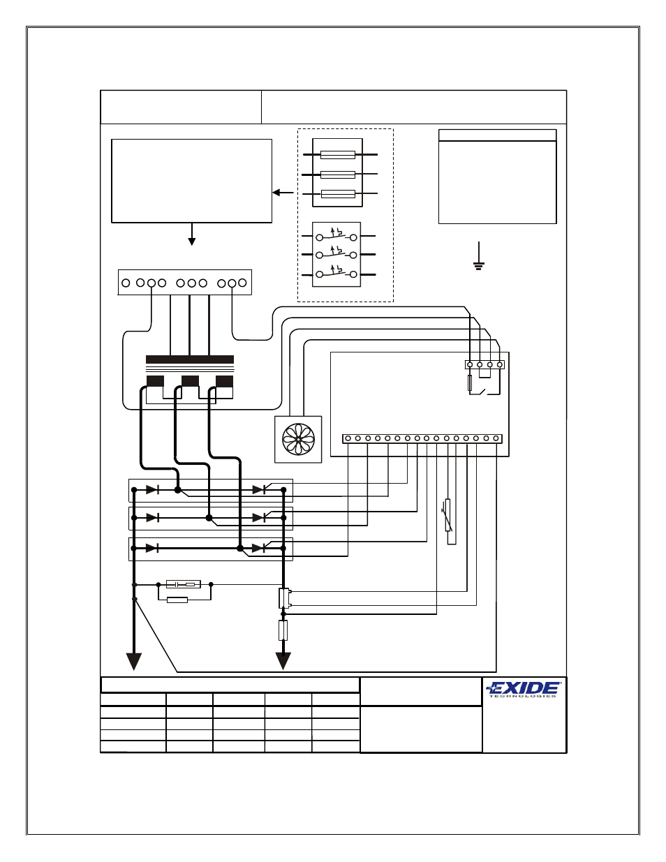
APPENDIX D
bl '0'
CON1
FS1
1
2
3
4
bl
gy
bl
br
PCB1
br
bk
rd
bl
wh
wh '0'
wh '1'
bl '1'
wh '2'
bl '2'
Shunt
bl gy
+
_
bl
FS2
16
wh '
2
'
wh '1
'
bl
'1'
wh '0'
rd
wh
bl
rd
rd
bk
CO
N 5
1
2
3
4
5
6
7
8
9
10
11
12
13
14
15
bl
'2'
bl
'0'
If any errors are apparent within this
diagram please inform CMP
engineering.
CMP Batteries Ltd,
Charger Division,
Unit 2 Pisces,
Mosley Road,
Trafford Park,
Manchester.
M17 1PF.
Component No:
CLT6006
DRAWING TITLE:
GNB [UL] 3phase wiring diagram
KEY
bl
BLUE
bk
BLACK
br
BROWN
gy
GREY
rd
RED
wh
WHITE
YL/G
YELLOW / GREEN
T1
YL/G
DRAWING No: 4 - CMP - 2600 - 01 - WD - E
Drawn by:
Checked by:
MOD No:
REV:
Trev Peacock
13 12 02
-
B
C000007
Materials:
White Polypropylene 60u PP198 TC
Clear Overlaminate 60u PP20
Adheasive:
AP51
Size:
A5 (210mm x 147mm)
Text:
As shown
Colour:
Black on white
OR
L2
L1
L3
L1
L2
L3
L2
L1
L3
L2
L1
L3
Trev Peacock
10 12 03
-
C000044
C
Trev Peacock
19 12 03
-
C000045
D
20
8V
20
8V
20
8V
24
0V
24
0V
24
0V
48
0V
48
0V
48
0V
N
For 208V input connect to 208V
connections on T1
For 240V input connect to 240V
connections on T1
For 480V input connect to 480V
connections on T1
Trev Peacock
17 03 04
-
C000068
E
Sales
• Service • Recycling 1-888-563-6300
16