Chapter 5 communication, Communication – Eaton Electrical Powerware 9130 User Manual
Page 61
Eaton
®
9130 UPS (700–3000 VA) User's Guide
S
164201718 Rev 2
www.powerware.com
53
Chapter 5
Communication
This section describes the:
S
Communication ports (RS-232 and USB)
S
Connectivity cards
S
Remote Emergency Power-off (REPO)
S
Relay output contacts
S
Programmable signal inputs
S
Modem operation
S
Powerware LanSafe
®
Power Management Software
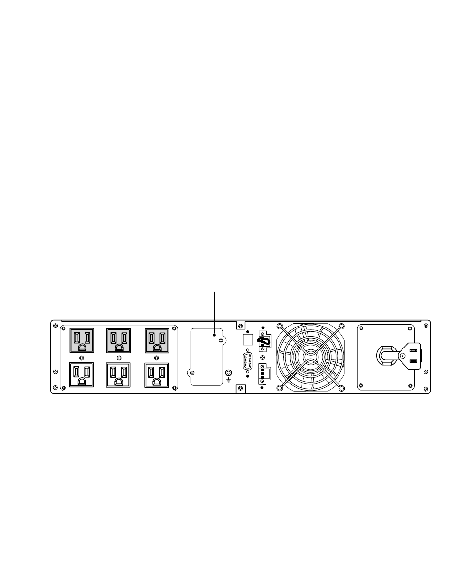
Figure 18 shows the location of the communication options and control
terminals on a typical UPS.
See “Rear Panels” on page 91 for rear panel diagrams for each model.
Communication Bay
USB
REPO
RS-232
Standard Relay Output Contact
Output
Input
Figure 18. Communication Options and Control Terminals (PW9130L1000R-XL2U Model Shown)