Accessories installed, Bida series instruction manual, Bida-rf return filter set – Blonder Tongue BIDA 5400 Series Indoor Distribution Amplifier (750 MHz, 30 dB) User Manual
Page 6: Bida-ra return amplifier, Bida-fa-(*) flat attenuator, Bida-ce cable equalizer, Accessory identification
6
BIDA Series
Instruction Manual
Note: Field service information is provided only for qualified com mer cial equipment installation per son nel.
There are no user ser vice able parts in the BIDA.
INFORMATION BELOW IS FOR QUALIFIED INSTALLATION PERSONNEL ONLY
THE BIDA AMPLIFIER CAN EASILY BE MOUNTED TO ANY FLAT SURFACE. FOUR PRE-DRILLED MOUNTING HOLES ARE PROVIDED. USE #10 SCREWS
(NOT SUPPLIED).
Field Installable Optional Modules
.
(Take care not to bend jack pins when plugging in modules - view orientation of pins through holes provided - pins are polarized to prevent wrong
installation - see Location Diagram). Leakage-current and/or resistance measurements should be made by service technician after repairs are com-
pleted to determine that exposed parts are acceptably insulated from the supply circuit.
BIDA-RF Return Filter Set
Stock No. 54071
Plug-in return filter adds passive reverse path to BIDA series
amplifiers. Each BIDA-RF Plug-in contains a high pass (47-750 MHz)
and a low pass (5-30 MHz) filter element with a common (5-750
MHz) connecting point. A sheet metal cover is mounted over the
circuitry to improve stability and prevent accidental detuning during
shipping, handling, and installation. The filters separate sub-band
(return) signals from VHF (forward) signals for processing within the
amplifier. Two identical BIDA-RF units in the set make an amplifier
bi-directional. A passive-return jumper wire is supplied to complete
the sub-band path. The jumper wire is to be inserted between J 12
and J 16. (See location diagram). Before inserting filters, remove the
two factory installed VHF (forward) bypass jumpers, W2 (between
J1 & J2) and W5 (between J9 & J10) and remove any residual RTV
sealant, used to hold jumpers in place, which remains on the board
surface.
BIDA-RA Return Amplifier
Stock No. 5402
Plug-in return amplifier adds reverse path gain to BIDA series
amplifiers. The BIDA-RA is a sub-band (5-30 MHz) amplifier with
24 dB gain. It contains a 12 dB variable slope control and a 12 dB
variable gain control. A BIDA-RF return filter set (54071) is required
to complete the system. The passive return jumper is discarded.
BIDA-FA-(*) Flat Attenuator
Stock No. 5411
Plug-in flat attenuator pad for reducing forward gain in BIDA series
amplifiers. The BIDA-FA is available in fixed values of 1 thru 20 dB in
increments of 1 dB. Before inserting, remove the factory installed "0
dB" jumper wire W3 (between J3 & J5) and remove any residual RTV
sealant, used to hold jumpers in place, which remains on the board
surface.
* Specify dB value.
BIDA-CE Cable Equalizer
Stock No. 5475 (for BIDA 550 MHz) = BIDA CE-5-(*)
Stock No. 5477 (for BIDA 750 MHz) = BIDA CE-7-(*)
Plug-in cable equalizer for increasing forward slope in BIDA
series amplifiers. The BIDA-CE provides attenuation that varies
inversely with frequency to correct inherent tilt of coaxial
cable used in distribution systems. A sheet metal cover is
mounted over the circuitry to improve stability while preventing
accidental detuning during shipping, handling, and installation.
The BIDA-CE is available in fixed values of 3, 6, 9, 12, 15 or 18
dB. Before inserting, remove the factory installed “0dB” jumper
wire W4 (between J6
& J8) and remove any residual RTV sealant, used to hold jumpers
in place, which remains on the board surface.
* Specify dB value.
Note: The unit is shipped with 18 gauge jumpers which are not
re-installable. Do not remove jumpers except when installing
optional equipment modules.
For future reference, it is recommended that the type and value
of the accessories installed in the BIDA be marked in the space
provided on the front panel. The full sized reproduction below
may also be copied and used for that purpose.
Accessories Installed
Flat Attenuator
____________dB
Cable Equalizer
____________dB
Return Filter
____________
Return Amplifier
____________
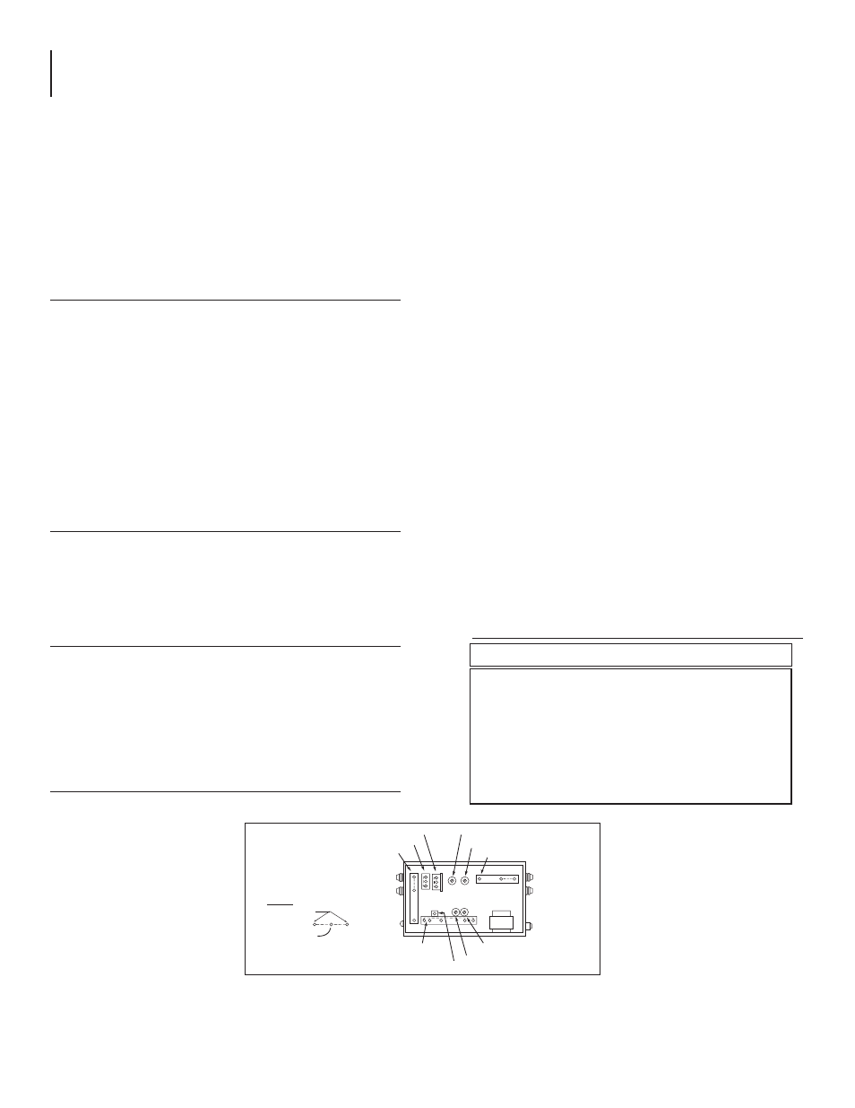
INPUT
TEST POINT
PILOT LIGHT
RETURN AMPLIFIER
REVERSE SLOPE
REVERSE GAIN
AMPLIFIER BALANCE(Factory Preset - Do Not Adjust)
FUSE
OUTPUT
TEST POINT
FORWARD GAIN
FORWARD SLOPE
CABLE EQUALIZER
Jumper Wire
(Alternate Config.)
Pin Jack Sockets
KEY:
RETURN FILTER
RETURN FILTER
FLAT ATTENUATOR
Figure 2. Module and Control Location Diagram (Top View)
Accessory Identification