Unit mounting – Energy Tech Laboratories DSH User Manual
Page 7
FORM 145.32-IOM1 (908)
7
JOHNSON CONTROLS
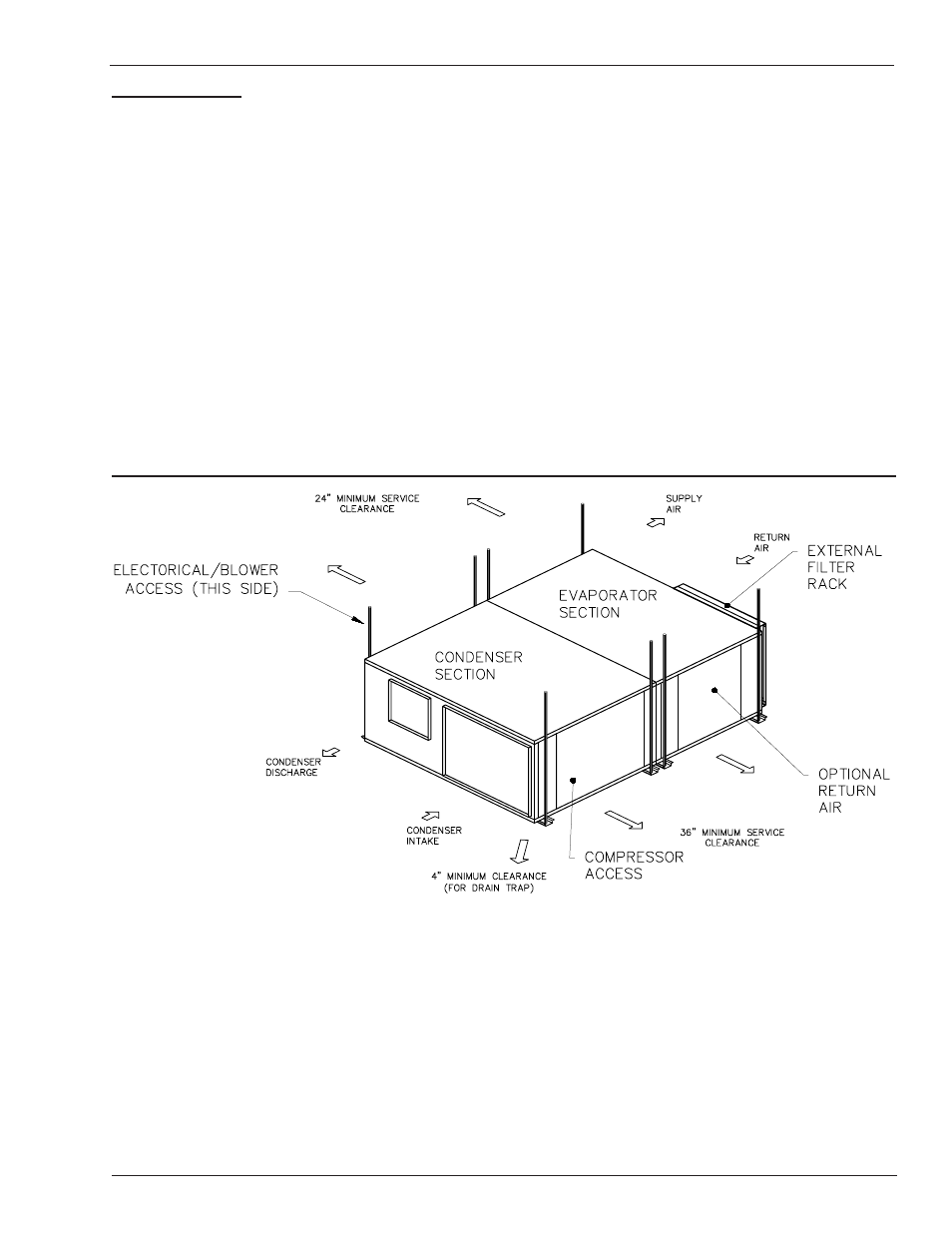
UNIT MOUNTING
The 2 through 5 ton unit consist of an evaporator and
condenser module. These two modules are rigidly at-
tached by a joining strip across the top of the two cabinet,
and two long side cross-member angles which bridge the
mounting channels on the bottom of the unit. These units
may be field split to allow for passage through doors,
elevators, hallways, etc. Alternatively, the units may be
installed as a split system after separation.
Units may be either hung, or floor mounted. If unit is to
be hung, use all mounting points indicated - regardless
if unit is installed as a package or split system (See unit
dimension drawings). Use of 1/2in. dia hanger rods is
recommended. Ensure the attachment point of the rods
to the building structure is sufficient to support the unit
weight. In order to ensure efficient condensate drain-
age, the unit may be pitched towards the evaporator
end of the unit.
A minimum of 4-in. clearance is required under the unit to
allow for trapping of the evaporator condensate drain.
Floor mounted units should be secured on a solid, level
pad. The use of isolating vibro-pads at several points
under the bottom mounting channels is recommended.
Ensure that provision is made for clearance to install a
trap on the condensate drain outlet.