Operating instructions con’t, Swivel lockout, Swivel release – SAF-HOLLAND XL-PH354 Swivel Type Automatic Coupler User Manual
Page 2: Swivel release con’t coupling sequence
OPERATING INSTRUCTIONS
con’t
4.
Release primary lock. While holding the secondary
lock handle in the open position, rotate the primary
lock handle rearward. The coupler jaw is immediately
free to rotate down and open.
5.
Remove drawbar. Uncouple the trailer by removing
the drawbar from the coupler throat.
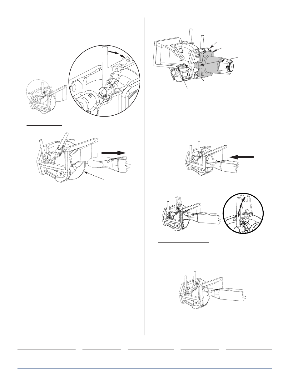
SWIVEL LOCKOUT
To lock the coupler frame and prevent rotation:
1.
Locate the spring–loaded roll pin on the curbside
center of the coupler frame.
2.
Rotate the coupler frame until the spring–loaded roll
pin is aligned with the matching hole in the mounting
sleeve flange.
3.
Push roll pin into the matching hole in the mounting
sleeve flange and rotate the roll pin up into the detent
position.
4.
Coupler frame is now locked into position.
SWIVEL RELEASE
To release the coupler frame and allow rotation:
1.
Locate the spring–loaded roll pin on the curbside
center of the mounting flange.
2.
Rotate the roll pin down and out of the detent
position. (It may be necessary to push the roll pin
forward to assist release from the detent position.)
3.
The spring–loaded roll pin will disengage from the
mounting sleeve flange and allow rotation of the
coupler frame.
Copyright © October 2005 • The Holland Group, Inc.
Holland USA, Inc. Facilities:
Dumas, AR
Muskegon, MI
Holland, MI
Warrenton, MO
Monroe, NC
Wylie, TX
Ph: 888-396-6501
Fax: 800-356-3929
Holland International, Inc.
Holland, MI
Phone:
616-396-6501
Fax:
616-396-1511
Holland Equipment, Ltd.
Norwich, Ontario • Canada
Phone:
519-863-3414
Fax:
519-863-2398
Holland Hitch of Canada, Ltd.
Surrey, British Columbia • Canada
Phone:
604-574-7491
Fax:
604-574-0244
Holland Hitch of Canada, Ltd.
Woodstock, Ontario • Canada
Phone:
519-537-3494
Fax:
800-565-7753
SPRING–LOADED ROLL PIN
DETENT POSITION
MOUNTING SLEEVE
XL-PH354 Rev A
2
SWIVEL RELEASE
con’t
COUPLING SEQUENCE
1.
With coupler jaw in the open position and lock
indicator disengaged, insert drawbar into the throat of
the coupler with sufficient force to rotate the coupler
jaw around the drawbar eye activating the lock. Both
the primary lock handle and the secondary lock
handle will return to their locked positions when
completely coupled to the drawbar.
2.
Engage visual indicator. Rotate visual indicator
(shown below) toward the primary lock handle.
3.
Verify coupling is secure. Recheck that the primary
lock handle is in the vertical position, the secondary
lock handle has also rotated to the vertical position
(flat against the housing) and the visual indicator is
positioned across both sides of the primary lock
handle.
COUPLER JAW
MOUNTING
SLEEVE FLANGE
HOLE LOCKOUT
COUPLER FRAME