Operation – Exmark Turf Tracer 4500-528 User Manual
Page 19
Operation
Adjusting the Cutting Height
WARNING
When the two front support rod hairpins are
removed from the mower deck, the weight of the
tractor section may cause the front frame of the
unit to rise suddenly. If the unit rises suddenly,
injury may occur.
Securely hold down the front of the unit when the
front support rod hairpins are removed.
The cutting height of the mower deck is adjusted
from 1 1/2 to 4 1/2 inches (3.81 cm to 11.4 cm) in
1/2 inch increments.
1. Stop the machine and move the drive levers to the
neutral locked position.
2. Disengage the PTO.
3. Engage the park brake.
4. Stop the engine, remove the key and wait for all
moving parts to stop.
5. Install hairpin clips in the holes for the desired
cutting height. See Figure 6.
Important: To maintain correct cutting
height and rake, check the following for
proper adjustment.
A. The front and rear hairpins are in the same
holes with the proper spacers under the hair
pins. See Figure 6.
Figure 6
1.
Deck support pin
2.
Cutting Height
B. The tire pressures are set as directed in Check
Tire Pressures in the Maintenance section.
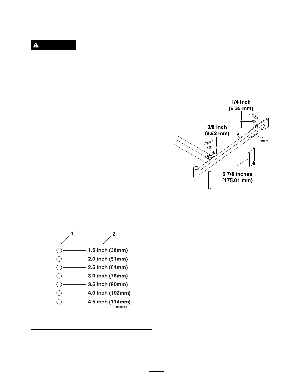
C. The length of the rear deck support link
assemblies average 6.89 inches (approximately
6 7/8 inches) (175.01 mm) from the center of
the balljoint to the center of the farthest hole.
See Figure 7.
Note: All four pins must equally support the
weight of the deck. Adjustment in the length
of the rear deck support assemblies may be
necessary. If one side is longer than 6.89
inches (approximately 6 7/8 inches) (175.01
mm), than the opposite side must be shorter
by the same amount.
Figure 7
Left Hand Side Shown
Adjusting the Anti-Scalp Rollers
It is recommended to change the anti-scalp roller
position, when the height of cut has changed.
1. Stop the machine and move the drive levers to
the neutral lock position.
2. Disengage the PTO.
3. Engage the park brake.
4. Stop the engine, remove the key and wait for all
moving parts to stop.
5. After adjusting the height of cut, adjust the
anti-scalp rollers by removing the spring disc
washer and bolt (see step 7).
6. Adjust anti-scalp rollers for Normal Operating
Conditions. Place rollers in one of the positions
shown in Figure 8. Rollers will maintain 3/4
inches (19 mm) clearance to the ground to
minimize gouging and roller wear or damage.
Note: For Maximum Deck Flotation, place
rollers one hole position lower. Rollers should
19