Rose Electronics CrystalLink USB 2.0 CATx User Manual
Page 9
INSTALLATION
Installation and Operations Manual
5
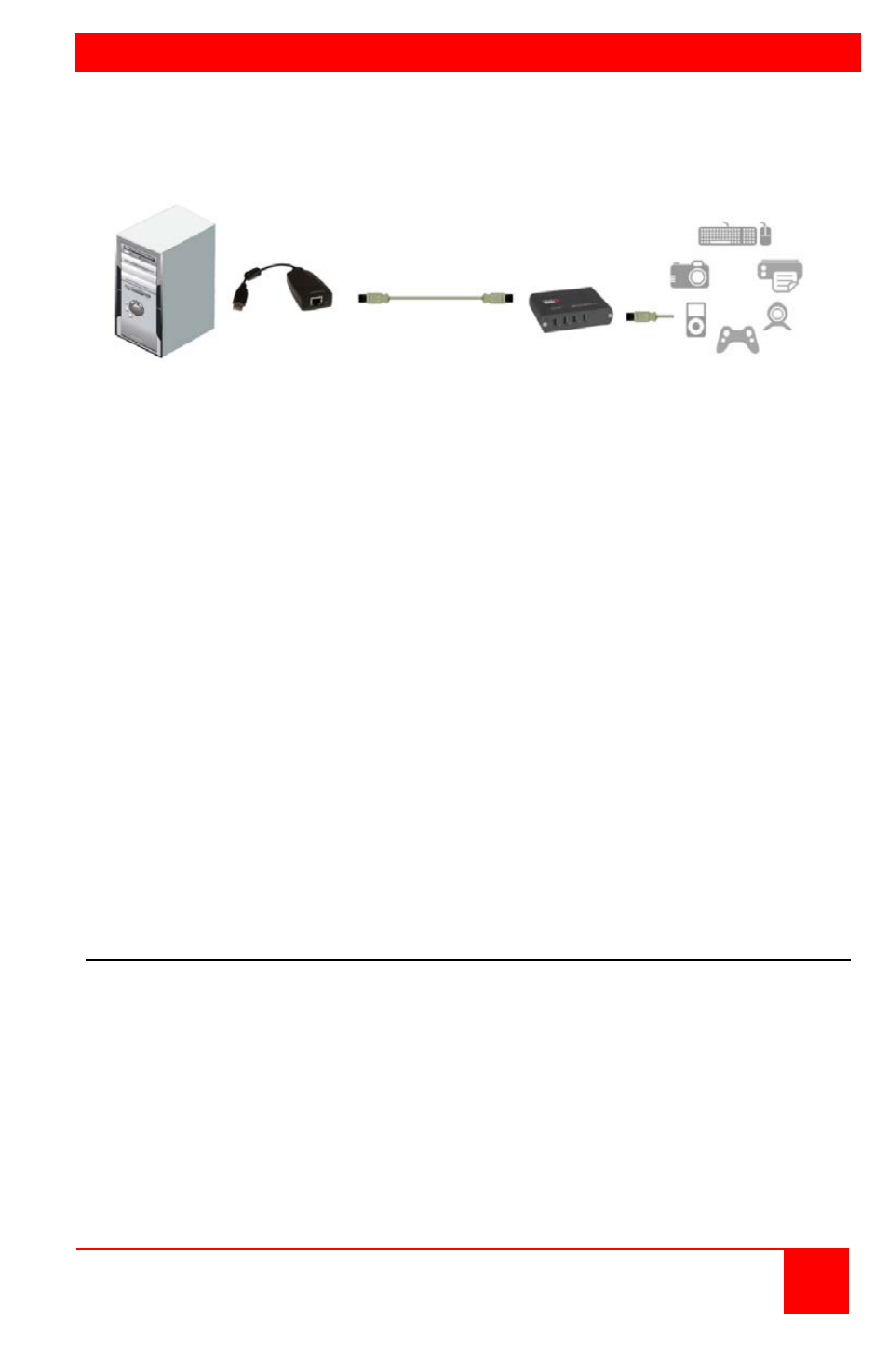
Figure 1 outlines the basic installation of the CrystalLink USB 2.0 CAT5
extender. The installation steps below are a guide to properly install the
units and cabling.
Figure 1. Installation
Before you install the CrystalView USB 2.0 CAT5 extender, it is
recommended that you pre-plan you system layout, consisting of the
placement of the computer, the routing of the CAT5 cabling, and the
location of the USB device(s).
1. Connect the transmitters USB Type A cable connector to an unused
USB port on the computer.
2. Connect the provided power adapter to the power jack on the receiver
unit. Use only the furnished power adapter. Other power adapters may
cause permanent damage to the receiver unit and void the warranty.
3. Connect up to 330 feet (100M) of industry standard UTP CAT5 or better
cable terminated with RJ45M connectors to the transmitter’s and
receiver’s RJ45F port.
4. Connect the provided power adapter to a 100/240 V AC 50 – 60 Hz
power source.
5. Install any required software to operate the USB device(s).
6. Connect the USB peripherals to the USB Type A connectors on the
receiver unit.
Verifying the installation
1. Check that the USB device is detected and installed properly in the
operating system.
2. Verify that the CrystalView USB 2.0 extender has installed correctly by
opening the Device manager and expand the USB controller section
(click on the + sign). You should see the unit listed as a Generic USB
Hub.
3. Verify the Power, Host, and Link LEDs are on and the Activity LED is
blinking. If any LED is off, check the CAT5 cabling.
Transmitter Receiver
CAT5 Cable
USB 1.1 or 2.0
peripherals