Installation, Installation – singlelink / single video – Rose Electronics CrystalView DVI Plus User Manual
Page 10
INSTALLATION
4
CrystalView DVI Plus Installation and Operations Manual
Installation – Singlelink / Single Video
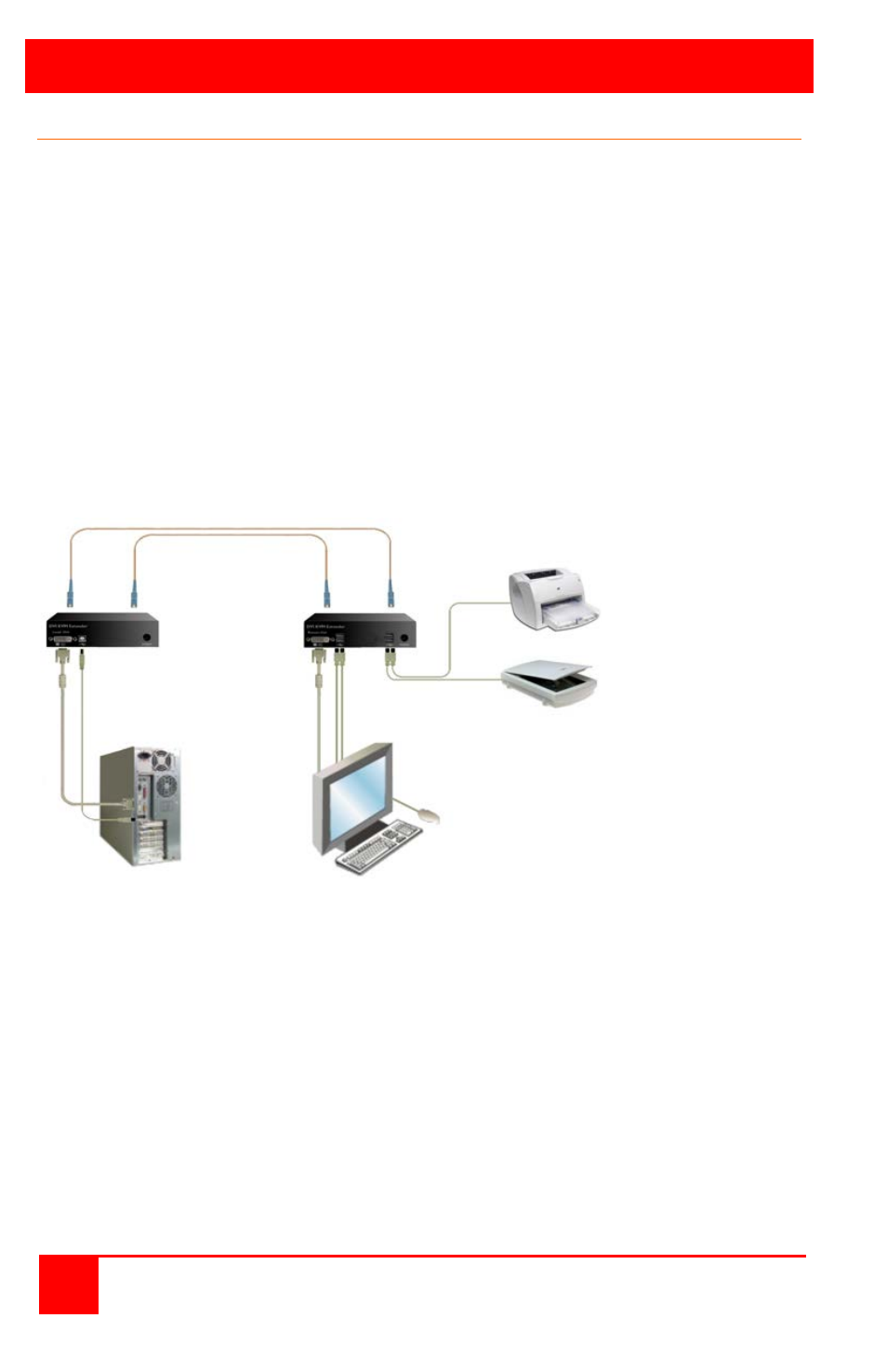
The example in figure 2 shows a typical installation for the Singlelink / Single Video
model. It is recommended that all equipment be turned off. The cables needed for
this installation are:
1- DVI-D MM video cable
1-USB Type A to Type B
2-
Multimode fiber cables 50µm or 62.5µm. E.g. I-V(ZN)H 2G50
(In house patch cable) or I-V(ZN)HH 2G62.5 (In house Breakout cable)
or I/AD(ZN)H 4G50 (In house OR Outdoor Breakout cable, stress
resistant) or A/DQ(ZN)B2Y 4G62.5 (Outdoor cable, stress resistant with
protection against animal biting)
A point to point connection is required for the fiber cables. Having one or
more patch panels in the line is possible and allowed. Not allowed is a
connection from the fiber link interface to any other products, especially
telecommunications or network equipment.
Figure 2. Installation – Singlelink / Single Video
1. Connect a DVI-D MM video cable from the DVI-D video card connector
to the corresponding connector on the local unit.
2. Connect a USB Type A to Type B cable from the USB connector on the
computer to the USB Type A connector on the local unit.
3. Connect a DVI monitor, USB keyboard and USB mouse to the
corresponding connectors on the remote unit.
4. Connect two fiber cables from the local unit to the remote unit.
5. Attach your USB 2.0 compatible devices to the USB connectors on the
remote unit.
6. Plug-in the two supplied power adapters to the local and remote units
(5V / 2.4A to transmitter, 5V / 4A to receiver)
7. Power on the monitor, remote unit, local unit, and the computer
Local Remote