Shaft mounted cam limit switch – Eaton Electrical TRS 3064 User Manual
Page 11
Item
No.
6.
20.
22.
23.
24.
25.
26.
27.
28.
28A
29.
30.
31.
32.
33.
33A
34
38.
40.
41.
42.
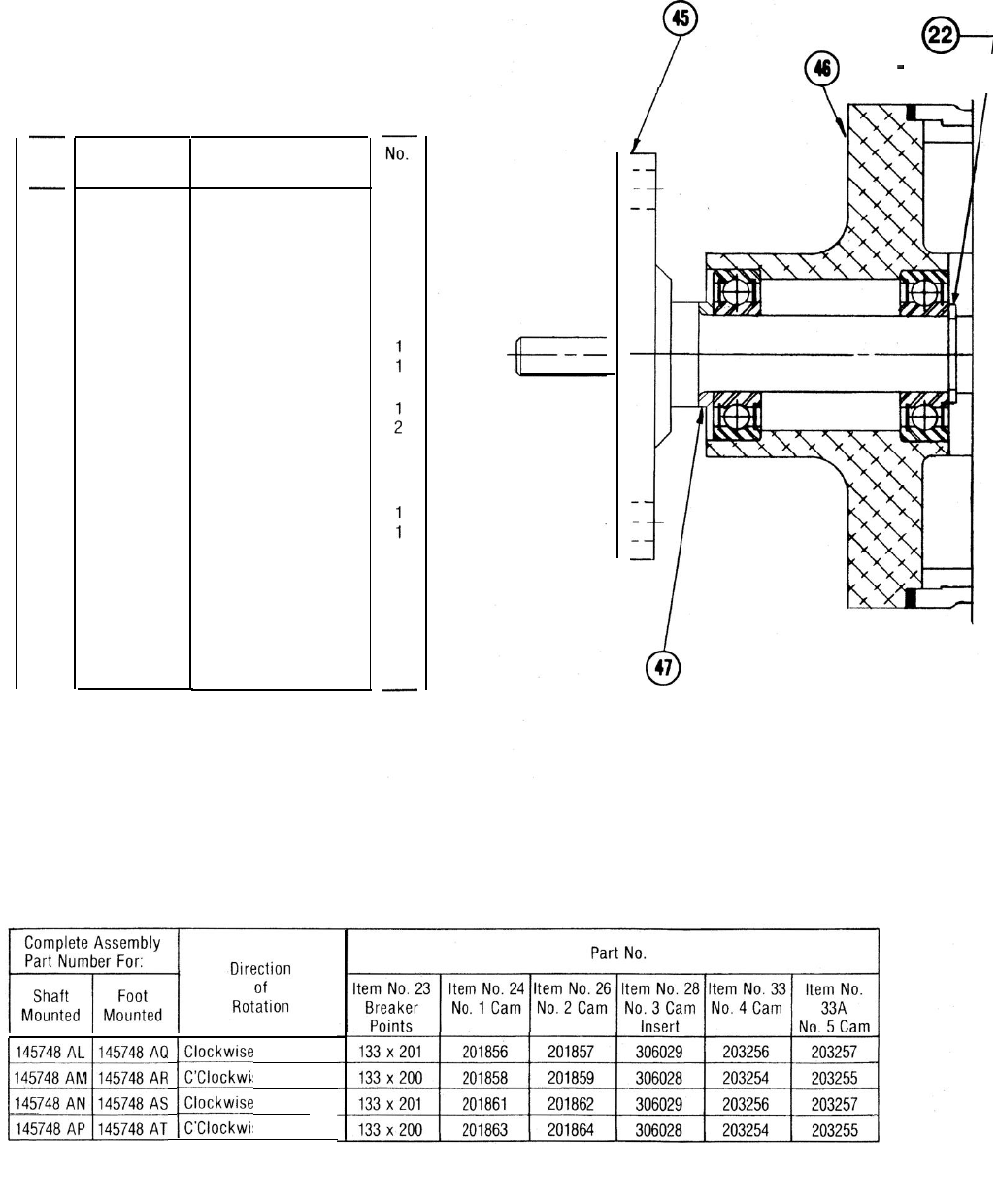
45.
46.
47.
Part No.
Description
302276
159 x 41
139 x 12
See table C
See table C
201854
See table C
201869
See table C
306030
203003
61 x 22
412230
409346
See table C
See table C
119 x 23
507137
153 x 530
203107
404583
411367
405330
203351
Shaft
Bearing
Snap ring
Breaker points
No. 1 cam
Washer
No. 2 cam
Cam adjusting sleeve
No. 3 cam insert
No. 3 cam
Cam adjusting knob
Jam nut
End cap
Bridge
No. 4 cam
No. 5 cam
Felt seal
Mounting plate
Flat washer
Spacer
Housing
Shaft
Housing
Spacer
Req.
1
2
1
4
1
1
1
1
1
1
1
1
1
1
1
1
1
1
The part no. for the complete assembly is stamped on
the timer decal. Identify the timer with this number
when specifying component parts.
i
s
e
145748 AP 145748 AT C’Clockwise 30° Dwell
22
1 Req’d.
I
SHAFT MOUNTED
CAM LIMIT SWITCH
TABLE C