ROCKINGER RO 825 A User Manual
Page 4
ROCKI NG E R
Member of JOST-World
15
GB
1
1.. F
Fiittttiin
ng
g
R
RO
O
i
i
8
82
25
5 A
A
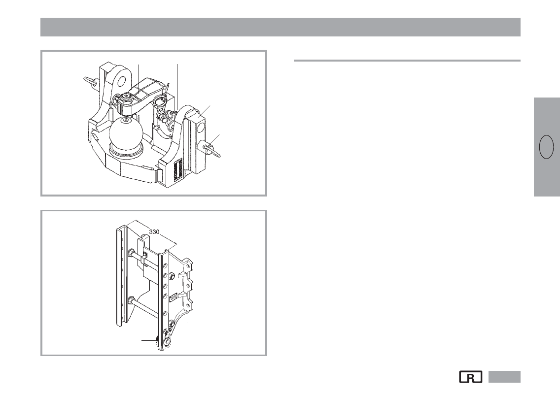
1. Fitting
The ball coupling is supplied in a ready-to-use condition.
x Observe the relevant regulations.
x Remove locking pin (D, see fig. 2) as necessary
x Remove linchpin and pin (B).
x Place the ball coupling in the guide rails of the drawbar.
Attention:
Hold the ball coupling with a firm grip. Risk of accident!
x Fix the ball coupling at the desired height with the pins (B) on the
left and right.
x Secure the ball coupling with the linchpins on the left and right.
Note:
The guide rail (F) of the ball coupling may not project
beyond the guide rails of the drawbar.
(Exception: Fendt drawbar – see Fendt Operating Instructions)
The ball coupling can also be fitted above the power take-off shaft
(overhead suspension). Observe the instructions of the tractor
manufacturer for the permissible vertical load (generally 2 t).
Fig. 1
Fig. 2
D
Track
width
(SW)
N
R
F
B