Riello UPS MultiCOM 401 User Manual
Page 14
14
PZD-
PART
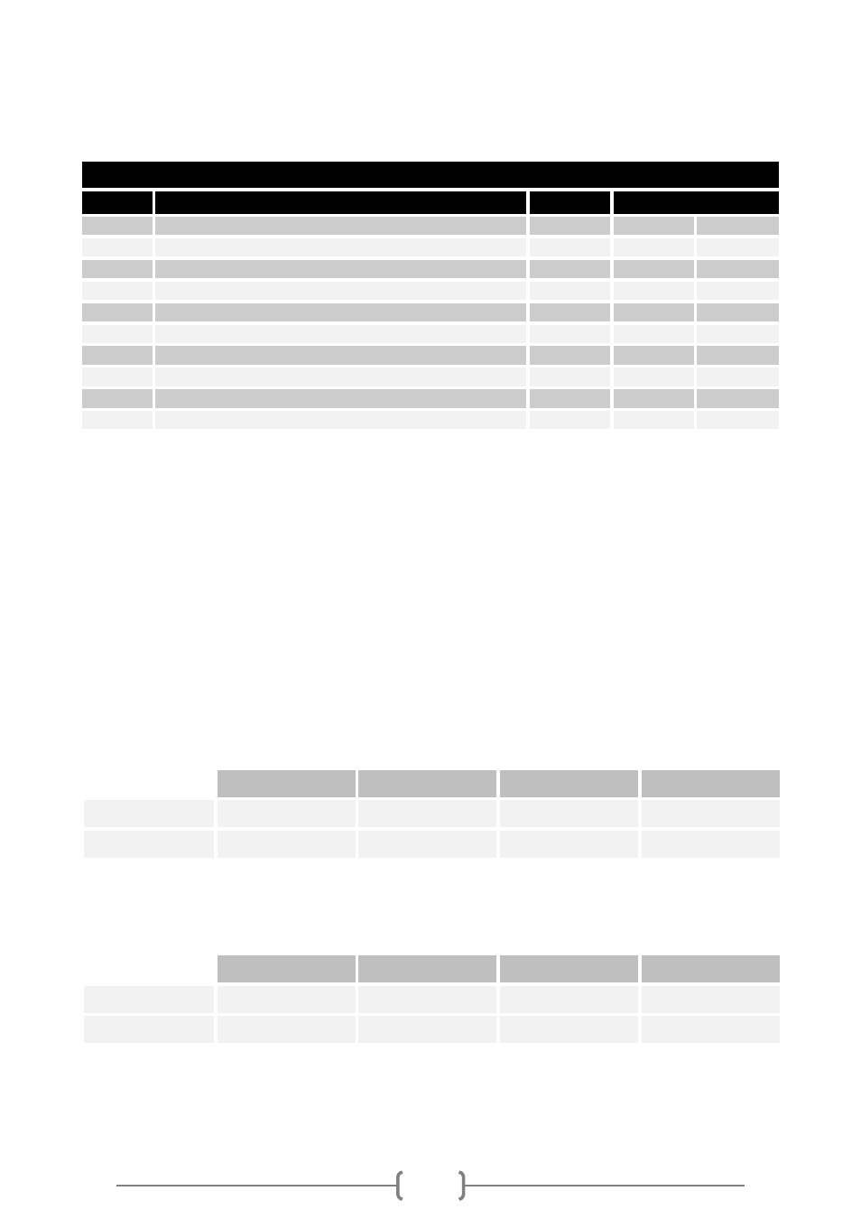
MultiCOM 401 is provided with a default PZD input configuration:
DEFAULT PZD INPUT CONFIGURATION
DESCRIPTION
Unit
Index
PZD1
UPS states (see the STATES table)
Flag
1
0x0001
PZD2
UPS states (see the STATES table)
Flag
2
0x0002
PZD3
Input mains voltage V1
V
12
0x000C
PZD4
Input mains voltage V2
V
13
0x000D
PZD5
Input mains voltage V3
V
14
0x000E
PZD6
Load phase L1
%
38
0x0026
PZD7
Load phase L2
%
39
0x0027
PZD8
Load phase L3
%
40
0x0028
PZD9
Remaining back-up time
Minutes
54
0x0036
PZD10 Remaining Battery Capacity
%
52
0x0034
In order to have different UPS parameters in PZD-part, the default configuration can be changed
by user as described below.
U
SER DEFINED
PZD
SLOTS
For configurations the standard parameters 915 and 916 are used to define which values are
transferred in these slots.
Parameter 915 defines output and 916 input direction. Both parameters 915 and 916 are of array
type and the subindex is used to reference the PZD slot (subindex 1 references PZD slot 1,
subindex 2 references PZD slot 2, ... subindex 10 references PZD slot 10). Parameters of type
word and byte can be selected (there is an implicit conversion byte-word). Not used PZD slots are
marked with 0 in the parameters 915 and 916.
EXAMPLES
Set input PZD3 with Input mains voltage V1 (index 12 [0x000C] UPS PARAMETER):
PKW
Word 0
Word 1
Word 2
Word 3
Output:
0x7394
0x0300
xxxx
0x000C
Input:
xxxx
xxxx
xxxx
xxxx
Word 0 → Index used 0x394 (916dec)
Word 1 → sub-index YY=03 (PZD3)
Word 3 → Value = index of Input mains voltage V1 in UPS PARAMETER table
Set input PZD10 with Battery voltage (index 48 [0x0030] UPS PARAMETER):
Word 0
Word 1
Word 2
Word 3
Output:
0x7394
0x0A00
xxxx
0x0030
Input:
xxxx
xxxx
xxxx
xxxx
Word 0 → Index used 0x394 (916dec)
Word 1 → sub-index YY=0A (PZD3)
Word 3 → Value = index of Battery voltage in UPS PARAMETER table