1234 o n, Technical specifications, Specifiche tecniche – RISCO Group Wireless IR Beam RWT74 User Manual
Page 2: Especificaciones técnicas, Spécifications techniques
12
-2-
TC
RC
Rx
11
5 sec.
10
Rx
Tx
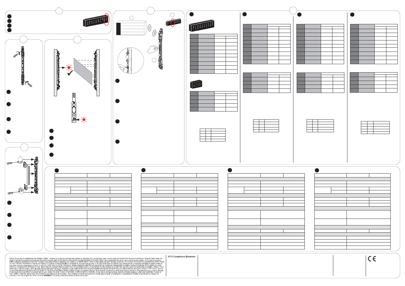
Perform IR detection test. Alarm LED should
light up during detection.
Test di rilevazione degli IR. Il Led Allarme deve
accendersi ad ogni rilevazione.
Realizar una prueba de detección del IR. El
LED de Alarma deberá encenderse durante la
detección.
Faire un test de détection IR. La LED d'alarme
devrait s'allumer lors d'une détection.
Tx + Rx
9
Lock the swivel screws on
both the Tx and Rx rails.
Make sure that the alignment
remains fixed.
Tirare le viti degli snodi su
entrambe le barriere.
Assicurarsi che durante
l’operazione non si
disallineino.
Fijar los tornillos de la rótula
en las dos barreras Tx y Rx.
Asegurarse de que se
mantiene la alineación.
Revisser les vis de
verrouillage de position des
rails Tx et Rx. S'assurer que
l'alignement reste fixe.
RISCO Group Limited Warranty
Contacting RISCO Group
RISCO Group is committed to customer service and product support. You can contact us through our website www.riscogroup.com or as follows:
United Kingdom
Tel: +44-(0)-161-655-5500
[email protected]
Italy
Tel: +39-02-66590054
[email protected]
Israel
Tel: +972-3963-7777
[email protected]
Spain
Tel: +34-91-490-2133
[email protected]
France
Tel: +33-164-73-28-50
[email protected]
USA
Tel: +1-631-719-4400
[email protected]
Belgium
Tel: +32-2522 7622
[email protected]
Brazil
Tel: +55-11-3661-8767
[email protected]
China (Shanghai)
Tel: +86-21-52-39-0066
[email protected]
© RISCO Group 05/2012 5IN1326 E
All rights reserved. No part of this
document may be reproduced in any
form without prior written permission
from the publisher.
Return to Normal mode: On the RC set Dipswitch 10 to OFF.
Per tornare in modalità Normale: Sull’RC riportare il Microinterruttore
10 in OFF.
Volver al modo Normal: en el RC poner el DIP 10 en OFF.
Se mettre en mode normal : Sur le RC, placer le Dipswitch 10 sur OFF.
SW10=OFF
RC
8
1 2
3 4
5 6
7 8
9 10
ON
Tx + Rx
13
Close the Tx and Rx rails
according to the A, B, C, D
order in the diagram
above.
Chiudere il Tx e l’Rx
seguendo i passi A, B, C,
e D del diagramma.
Cerrar las barreras Tx y
Rx según el orden
indicado en el diagrama
superior: A, B, C, D.
Fermer les rails Tx et Rx
en suivant l'ordre A, B, C,
D du diagramme ci-
dessus.
SW 6 SW 7 Interruption Time
OFF OFF 225ms*
OFF ON 450ms
ON OFF 675ms
ON ON 900ms
Table 1
Note the following:
i. The RC and TC setting must be identical.
ii. The RC and TC channels must be identical.
iii. Used to adjust the sensitivity to the surroundings
to avoid false alarms. Slower settings reduce
sensitivity.
iv. For walk test purposes the hold-off time will be
immediate and the Alarm LED will be on during
the first 10 minutes after installation.
v. Set the transmission strength according to the
distance between the RC and TC units.
Low signal: 0.5m-2m
High signal: 2m-5m
If 2 consecutive beeps are heard in Normal
mode, on the TC unit set SW 4 to ON.
Notare quanto segue:
i. La sensibilità dell’IR sull’RC e sul TC deve
essere identica.
ii. Il canale dell’RC e del TC deve essere identico.
iii. Usati per regolare il tempo di risposta
d’attivazione dei fasci per prevenire falsi allarmi.
La minor velocità riduce la sensibilità.
iv. Al fine di facilitare la prova di movimento durante
i primi 10 minuti dopo l’installazione sia il led di
allarme che la parte trasmittente saranno attivi.
v. Impostare questo Microinterruttore basandosi
sulla distanza che intercorre tra l’RC e il TC.
Segnale basso: 0.5m – 2m
Segnale alto: 2m – 5m
Se in modo normale di funzionamento vengono
riprodotti 2 toni acustici consecutivi, impostare
sull’unità TC il microinterruttore 4 su ON.
Tenga en cuenta lo siguiente:
i. La configuración del RC y TC debe ser
idéntica.
ii. RC y TC deben usar el mismo canal.
iii. Se utiliza para ajustar la sensibilidad al entorno
para evitar falsas alarmas. Las configuraciones
más lentas reducen la sensibilidad.
iv. Para facilitar la prueba de paseo, durante los
primeros 10 minutos tras la instalación el
tiempo de reposo será inmediato y el LED de
alarma se encenderá con cada detección.
v. Configurar la potencia de transmisión en
función de la distancia entre las unidades RC y
TC.
Señal Baja: 0.5 m – 2 m
Señal Alta: 2 m – 5 m
Si en el modo Normal escucha 2 pitidos
consecutivos, ponga el DIP 4 de la unidad TC
en ON.
A noter :
i. Les paramètres du RC et TC doivent être
identiques.
ii. Les canaux du RC et TC doivent être
identiques.
iii. Utilisé pour ajuster la sensibilité à
l'environnement pour éviter les fausses
alarmes. Un paramètre plus lent réduit la
sensibilité.
iv. Pour les besoins de la réalisation du test de
marche, le temps d’attente sera considéré
comme immédiat et la LED Alarme sera
allumée pendant les 10 premières minutes
après l’installation.
v. Paramétrer la puissance de transmission selon
la distance entre le RC et le TC.
Signal faible : 0.5m-2m
Signal élevé : 2m-5m
Si 2 bips consécutifs sont émis en mode
normal, mettre SW 4 sur ON sur le TC.
1 2 3
4 5 6
7 8 9
10
ON
SW4=ON
* = Default
* = Default
* = Por defecto
* = Par défaut
Hereby, RISCO Group declares that
this equipment is in compliance with
the essential requirements and other
relevant provisions of Directive 1999/
5/EC.
For the CE Declaration of Conformity
please refer to our website:
www.riscogroup.com.
Set communication between the RC (Rx Master unit)
and the security panel:
A. Set the panel to Learn mode.
B. Set Dipswitch 4 (Wall Tamper) on the RC to ON.
C. Press the tamper spring for 5 seconds.
D. If wall tampers have been previously connected (see
step 5) set Dipswitch 4 back to the OFF position.
Impostare la comunicazione tra l’RC (Rx Master) e la
centrale:
A. Porre la centrale in modalità “Learn” (Ascolto).
B. Spostare il Microinterruttore 4 dell’RC in ON.
C. Premere l’interruttore del Tamper per 5 secondi.
D. Se sono stati abilitati i Tamper antirimozione (vedere
punto 5) riportare il Microinterruttore 4 in OFF.
Configurar la comunicación entre el RC (unidad Rx
Maestro) y la central de seguridad:
A. Poner la central en modo Aprendizaje.
B. Poner el DIP 4 (Tamper Pared) del RC en ON.
C. Presionar el muelle del tamper durante 5 segundos.
D. Si se han conectado previamente los tampers (ver paso
5), volver a colocar el DIP 4 en la posición OFF.
Paramétrer la communication entre le RC (Rx Maître)
et la centrale de sécurité :
A. Mettre la centrale en mode Adressage
B. Placer le Dipswitch 4 (AP à l'arrachement) du RC sur ON.
C. Appuyer sur le ressort d'AP pendant 5 secondes.
D. Si l'AP à l'arrachement a été connectée (voir étape 5),
remettre le Dipswitch 4 en position OFF.
A
B
B
C
C
D
D
EN
IT
ES
FR
EN
IT
ES
FR
EN
IT
ES
FR
EN
IT
ES
FR
A
B
C
EN
IT
ES
FR
PANEL (Learn Mode)
Centrale (modalità “Learn”)
Central (Modo Aprendizaje)
Centrale (Mode Adressage)
EN
IT
ES
FR
Tx + Rx
Mode
SW
Function
1
RF Transmission High* Low
OFF ON
2
i
IR Beam Sensitivity
Low* High
3
ii
Channel A* B
4
Wall Tamper Enable Disable*
5
Alarm LED Enable* Disable
6 & 7
iii
Interruption Time See Table 1 See Table 1
9
iv
Hold Status 2.5 min* Immediate
10
Installation Mode Off* On
8
Supervision Time Every 65min Every 15min
Modo
SW
Funzione
1
Potenza segnale
Alta* Bassa
OFF ON
2
i
Sensibilità IR
Bassa* Alta
3
ii
Canale
A* B
4
Tamper Antirimozione
Abilitato
Disabilitato*
5
Led Allarme
Abilitato* Disabilitato
6 & 7
iii
Tempo di Risposta Vedi Tabella 1 Vedi Tabella 1
9
iv
Blocco trasmissioni
2,5 minuti* nessun blocco
10
Modalità Installazione
Off* On
8
Supervisione
Ogni 65 minuti Ogni 15 minuti
Modo
DIP
Función
1
Transmisión RF
Alta* Baja
OFF ON
2
i
Sensibilidad Haz IR
Baja* Alta
3
ii
Canal
A* B
4
Tamper Pared
Activado
Desactivado*
5
LED Alarma
Activado* Desactivado
6 & 7
iii
Tiempo Interrupción
Ver Tabla 1
Ver Tabla 1
9
iv
Tiempo Reposo
2,5 min* Inmediato
10
Modo Instalación
Off* On
8
Tiempo Supervisión Cada 65 min
Cada 15 min
Mode
SW
Function
1
Wall Tamper Enable Disable*
OFF ON
2
i
IR Beam Sensitivity
Low* High
3
ii
Channel A* B
4
v
IR Signal Strength High* Low
EN
Set the Dipswitches on both the RC and
TC units as required.
IT
Impostare i Microinterruttori delle barriere
come da necessità installative.
Modo
SW
Funzione
1
Tamper Antirimozione
Abilitato
Disabilitato*
OFF ON
2
i
Sensibilità IR
Bassa* Alta
3
ii
Canale
A* B
4
v
Potenza segnale IR
Alta* Bassa
RC
TC
SW 6 SW 7 Tempo di Risposta
OFF OFF 225ms*
OFF ON 450ms
ON OFF 675ms
ON ON 900ms
Tabella 1
ES
FR
Configurar los interruptores DIP de las
unidades RC y TC según sea necesario.
Placer les Dipswitchs sur les RC et TC
comme souhaité.
RC
TC
RC
TC
Modo
DIP
Función
1
Tamper Pared
Activado
Desactivado*
OFF ON
2
i
Sensibilidad Haz IR
Baja* Alta
3
ii
Canal A* B
4
v
Potencia Señal IR
Alta* Baja
Mode
SW
Fonction
1
AP à l'arrachement
Activé
Désactivé*
OFF ON
2
i
Faible* Elevé
3
ii
Canal A* B
4
v
Force du signal IR
Elevé* Faible
DIP 6 DIP 7 Tiempo Interrupción
OFF OFF 225ms*
OFF ON 450ms
ON OFF 675ms
ON ON 900ms
Tabla 1
SW 6 SW 7 Temps d'interruption
OFF OFF 225ms*
OFF ON 450ms
ON OFF 675ms
ON ON 900ms
Tableau 1
Sensibilité des
faisceaux IR
SW
* = Default
* = Default
* = Por defecto
* = Par défaut
IP Rating
RF Immunity
Storage Temperature
Operation Temperature
-20°C to +60°C (4°F to 140°F)
-25°C to +60°C (13°F to 140°F)
ENVIRONMENTAL
OPTICAL
Infrared Wave Length
PHYSICAL
Size (L x W x D)
Weight
RADIO FREQUENCY
RF Frequency
Modulation Type
Address Codes
ELECTRICAL
Batteries
Battery Life
Current
Consumption
(normal mode)
CR123A, 3.0V Lithium Battery
3 years typical, depends on usage
Receiver Transmitter
60μA[AVR]@3V
100μA[AVR]@3V
50μA[AVR]@3V
70μA[AVR]@3V
-
-
-
940nm
-
Technical Specifications
433.92/868.65MHz
ASK
16 million
0.5m unit: 500 x 40 x 42 mm
(19.6 in. unit: 19.6 x 1.5 x 1.6 in.)
1m unit: 1000 x 40 x 42 mm
(39.3 in. unit: 39.3 x 1.5 x 1.6 in.)
0.5m unit: 0.6kg (1.3lb)
1m unit: 1kg (2.2lb)
without batteries
According to EN 50130-4
IP65
0.5m unit:
EN
1m unit:
Classe IP
Immunità RF
Temperatura di stoccaggio
Temperatura operativa
Da -20°C a +60°C
Da -20°C a +60°C
AMBIENTALI
OTTICA
Lunghezza d’onda dell’infrarosso
FISICHE
Dimensioni (L x A x P)
Peso
FREQUENZA RADIO
Frequenza RF
Tipo di modulazione
Combinazioni per l’indirizzo
ELETTRICHE
Batterie
Autonomia batterie
Assorbimento
(modalità
Normale)
Batterie al Litio CR123A, 3.0V
3 anni, in base all’uso
Ricevente
Trasmittente
60μA[AVR]@3V
100μA[AVR]@3V
50μA[AVR]@3V
70μA[AVR]@3V
-
-
-
940nm
-
Specifiche Tecniche
433,92/868,65MHz
ASK
16 milioni
0,5m: 500 x 40 x 42 mm
1m: 1000 x 40 x 42 mm
0,5m: 0.6kg
1m: 1kg
Senza batterie
Conforme alla norma EN 50130-4
IP65
modello da 0,5m:
modello da 1m:
IT
Índice de Protección
Inmunidad RF
Temperatura Almacenamiento
Temperatura Funcionamiento
-20°C a +60°C (4°F a 140°F)
-25°C a +60°C (13°F a 140°F)
MEDIOAMBIENTALES
ÓPTICAS
Longitud Onda Infrarrojo
FÍSICAS
Tamaño (L x A x P)
Peso
RADIOFRECUENCIA
Frecuencia RF
Tipo de Modulación
Códigos de Dirección
ELÉCTRICAS
Baterías
Duración Batería
Consumo
Corriente
(modo normal)
CR123A, Pila Litio 3 V
3 años, dependiendo del uso
Receptor
Transmisor
60 μA [media] @ 3 V
100 μA [media] @ 3 V
50 μA [media] @ 3 V
70 μA [media] @ 3 V
-
-
-
940nm
-
Especificaciones Técnicas
433,92/868,65 MHz
ASK
16 millones
Unidad 0,5 m: 500 x 40 x 42 mm
(unidad 19,6’’: 19.6 x 1.5 x 1,6’’)
Unidad 1 m: 1000 x 40 x 42 mm
(unidad 39,3’’: 39.3 x 1.5 x 1.6’’)
Unidad 0,5 m: 0,6 kg (1.3 lb)
Unidad 1 m: 1 kg (2.2 lb)
sin baterías
Según EN 50130-4
IP65
Unidad 0,5 m:
Unidad 1 m:
ES
Indice de protection IP
Immunité RF
Température de stockage
Température de fonctionnement
-20°C à +60°C
-25°C à +60°C
ENVIRONNEMENTAL
OPTIQUE
Longueur d'onde IR
PHYSIQUE
Taille (L x l x P)
Poids
RADIO FREQUENCE
Fréquence RF
Type de modulation
Codes d'adresse
ELECTRIQUE
Batteries
Durée de vie de la batterie
Consommation
de courant
(mode normal)
Batterie Lithium CR123A, 3.0V
3 ans en utilisation normale
Récepteur
Transmetteur
60μA[AVR]@3V
100μA[AVR]@3V
50μA[AVR]@3V
70μA[AVR]@3V
-
-
-
940nm
-
Spécifications Techniques
433.92/868.65MHz
ASK
16 million
Unité de 0,5m : 500 x 40 x 42 mm
Unité de 1m : 1000 x 40 x 42 mm
Unité de 0,5m : 0,6kg
Unité de 1m : 1kg
Sans batterie
Selon la norme EN 50130-4
IP65
Unité de 0,5m :
Unité de 1m :
FR
FCC Note:
FCC ID: JE4WLT74
Only the 433,92 Mhz version is FCC
approved and to be sold in US.
The manufacturer is not responsible for
any radio or TV interference caused by
unauthorized modifications to this
equipment. Such modifications could
void the user’s authority to operate the
equipment
RC
+
I
1234
O
N
1
2
3
4
5
6
7
8
9 1 0
ON
1
2 3
4
ON
Mode
Fonction
1
Transmission RF
Elevé* Faible
OFF ON
2
i
Faible* Elevé
3
ii
Canal A* B
4
AP à l'arrachement
Activé
Désactivé*
5
LED d'alarme
Activé* Désactivé
6 & 7
iii
Temps d'interruption Voir tableau 1 Voir tableau 1
9
iv
Temps mort
2.5 min* Immédiat
10
Mode d'installation
Off* On
8
Temps de supervision
Sensibilité des
faisceaux IR
Toutes les
15 min
Toutes les
65 min
China (Shenzhen)
Tel: +86-755-82789285
[email protected]
Poland
Tel: +48-22-500-28-40
[email protected]