Fig.11, Fig.12 – Medal Sports SMUS1358406 User Manual
Page 13
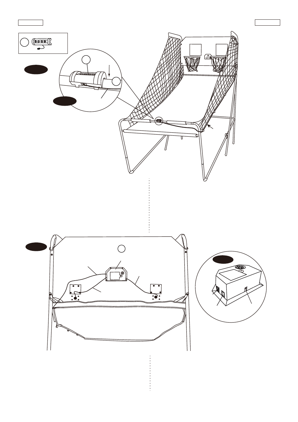
FIG. 11
FIG. 12
FIG.11
19. Attach the Control Box (#16) to middle of the Tube - K
(#11) as shown in FIG.11A.
20. Pass the Control Wire through the loops on the Ball
Return Net (#34) as shown in FIG.11.
FIG.11
19. Fije la Caja de Control (#16) en el medio de Tubo - K
(#11) como se indica en FIG.11A.
20. Pase el Cable de Contro a través de los circuitos de la
Redes de Vuelta de Pelota
(#34) como se indica
en FIG.11.
www.themdsports.com
1358406
12
(Continúe en la siguiente página.)
(Continued on the next page.)
Español
English
FIG.12
21. Connect the Sensor Wire from Switch Sensor (#15) to
the Electronic Scorer (#14) as shown in FIG.12 and
12A. Connect the Control Wire to the Electronic Scorer
(#14) as shown in FIG.12 and 12A.
FIG.12
21. Conecte el Cable de Sensor desde el Sensor de
Interruptor (#15) al Marcador Electrónico (#14) como se
indican en FIG12. Y 12A. Conecte el Cable de Control al
Marcador Electrónico (#14) como se indican en
FIG.12 y 12A.
14
Sensor wire
/ Cable de sensor
Sensor wire
/ Cable de sensor
Electronic Scorer
/ Cable de Control
Control Wire
/ Cable de Control
FIG. 12A
ON / OFF
ENCENDIDO / APAGADO
CONTROL
WIRE /
CONTROL
CABLE
VISITOR / VISITANTE
Control Wire
/ Cable de
Control
Control Wire
/ Cable de
Control
16
11
FIG. 11A
X1
16