Fig.3 – Medal Sports WM.com1416003 User Manual
Page 10
Español
www.themdsports.com
1416003
9
(Continúe en la siguiente página.)
(Continued on the next page.)
English
FIG.3
8. Attach the Electronic Scorer (#5) to the Scorer Support
(#6) using one Screw (#17) per Scorer Support.
See FIG. 3A.
9. Thread the wire from Goal Box (#11) through the
openings of the end aprons and support of the playfield
to insert the Wire into the Connect Box (#P3).
See FIG. 3B & 3C.
10. Attach the Goal Boxes (#11) to each End Apron using
three Screws (#7).
See FIG. 3.
11. Attach the Electronic Scorer (#5) to the Mainframe (#1)
using four Screws (#7).
See FIG. 3.
12. Thread the Wire of Electronic Scorer (#5) through the
opening of the Side Apron to the Connect Box (#P3),
and then plug the Scorer wire into the Connect Box
(#P3).
See FIG. 3C.
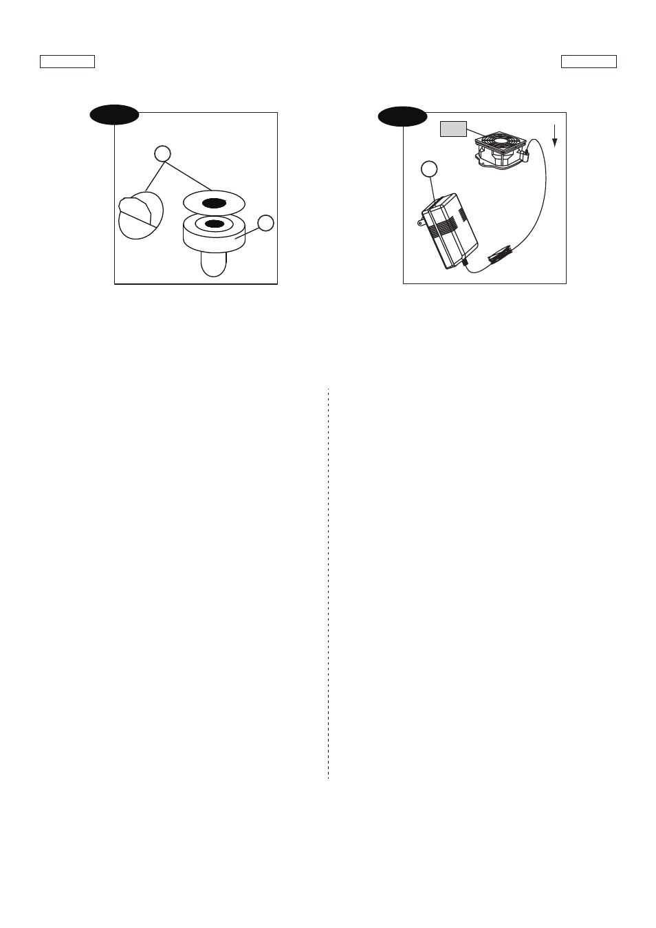
13. Tear off the backside paper of the Felt Pad (#10) and
stick them at the bottom of the Pushers (#9).
See FIG. 3D.
14. Insert the Adaptor (#16) into the DC Jack on the Motor
(#P1).
See FIG. 3E.
FIG.3
8. Adjunte el Marcador Electrónico (#5) al Soporte de
Marcador (#6) usando 1 Tornillo (#17) por Soporte de
Marcador.
Vea la FIG. 3A.
9. Enhebre el cable desde la Caja de Gol (#11) por las
aperturas de los delantales final y soporte del campo
de juego para insertar el Cable a la Caja de Conexión
(#P3).
Vea la FIG. 3B & 3C.
10. Adjunte el Cajas de Gol (#11) a cada Delantal Final
usando 3 Tornillos (#7).
Vea la FIG. 3.
11. Adjunte el Marcador Electrónico (#5) a las Unidad
Principal (#1)
usando 4 Tornillos (#7)
.
Vea las FIG. 3.
12. Enhebre el Cable del Marcador Electrónico (#5) por
las aberturas del Delantal Lateral a la Caja de
Conexión (#P3), y luego enchufe el cable del
Marcador a la Caja de Conexión (#P3).
Vea la FIG. 3C.
13. Arranque la trasera del papel de la Almohadilla de
Fieltro (#10) y péguelos en el fondo de Camello (#9).
Vea la FIG. 3D.
14. Inserte el Adaptador (#16) a DC Motor (#P1).
Vea la FIG. 3E.
P1
16
FIG. 3E
9
10
FIG. 3D