Instruction and maintenance manual, 9 adjustment, Lr l r – Marwin Valve UT Series Pneumatic Actuators User Manual
Page 9
INSTRUCTION AND MAINTENANCE MANUAL
MARWIN UT DESIGN 2011 PNEUMATIC ACTUATORS
Page 9 of 10
3170 Wasson Road * Cincinnati, OH 45209 USA
Phone 513-533-5600 * Fax 513-871-0105
e-mail:
–ww
Bulletin IM-UT Dsgn2011_1114
9 Adjustment
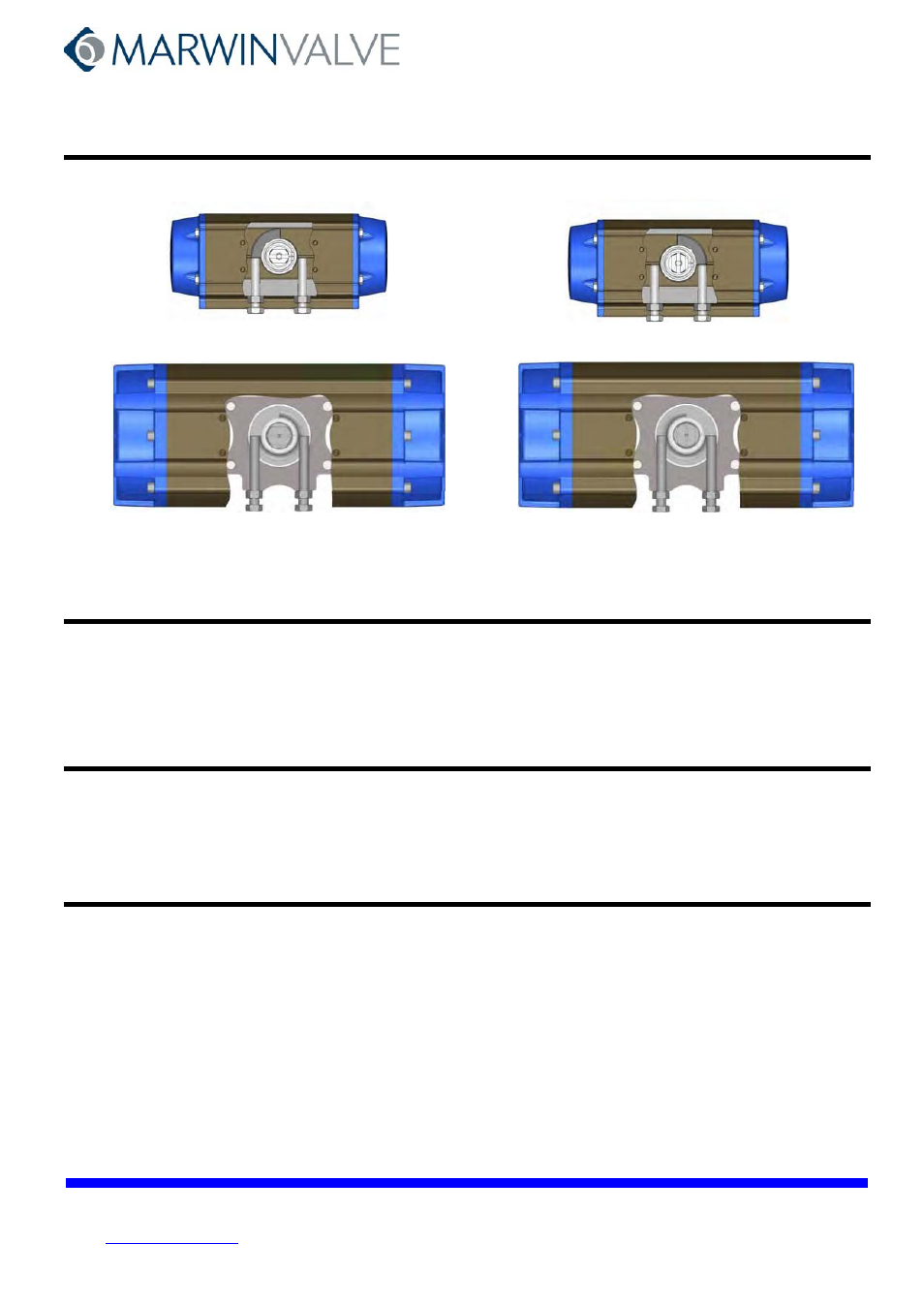
The 90° position (open) can be adjusted with the left screw (see Fig. 27). The 0° position (closed) can be adjusted with the right screw (see Fig. 28).
L
R
L
R
Fig. 27
Fig. 28
L
R
L R
NOTE: During the adjustment the pinion must not be blocked on the support.
9.1 Adjustment procedure, actuator in open position
•
Put the actuator in closed position.
•
Adjust by means of the left adjustment screw (L).
•
Put the actuator in open position and check the adjustment
•
Repeat until the desired adjustment is achieved.
•
Hold the screw in the correct position and tighten the nut.
9.2 Adjustment procedure, actuator in closed position
•
Put the actuator in open position (supply compressed air for spring return actuators).
•
Adjust by means of the right adjustment screw (R).
•
Put the actuator in closed position and check the adjustment (vent the air supply for spring return actuators).
•
Repeat until the desired adjustment is achieved.
•
Hold the screw in the correct position and tighten the nut.
10 Reversing Pistons
Industry convention is Clockwise to Close, CounterClockwise to open quarter turn valves. Standard actuator execution is for the spring force to
rotate the piston clockwise, which causes the valve to fail clockwise to close, in accordance with this convention. For fail open valves, pistons
should be reversed for the spring force to rotate the piston counterclockwise to open the valve, in order to maintain the industry convention.
To reverse the pistons, disassemble the actuator through Section 7.1 (UT-0 thru UT-6.5) or 7.2 (UT-7 and UT-7.5), step 8. It is not necessary to
remove the pinion in order to reverse the pistons.
Reassemble in accordance with Section 8.1 or 8.2, as applicable, except as follows: In step 7 or 8, put the pistons in opposite the orientation
shown in Fig. 17 or Fig. 23, and rotate the cylinder (1) in the counterclockwise direction. In step 9 or 10, the pistons have to be in OPEN
(contracted) position for spring insertion.