Assembly – Marwin Valve UT Series Pneumatic Actuators User Manual
Page 4
Spring Setting
Set
External Spring
Internal Spring
Air Supply, psi/(bar)
01
1
1
36 - 44 / (2.5 - 3)
02
2
0
44 - 58 (3 - 4)
03
1
2
58 - 73 (4 - 5)
04
2
1
73 - 80 (5 - 5.5)
05
2
2
80 - 87 (5.5 - 6)
Material Specifications - UT-0 thru UT-4.5
Item
Description
Material
Treatment
Qty. DA
Qty. SR
1
Body
Extruded Aluminum
Hard Anodized
1
1
2
Anti-Blowout Pinion
Steel
Nickel Plated
1
1
3* (R)
Lower Pinion O-Ring
NBR
1
1
4* (R)
Pinion Spacer Ring
POM Acetalyc Copolymer
1
1
5* (R)
Top Pinion O-Ring
NBR
1
1
6* (R)
Cam Spacer Ring
POM Acetalyc Copolymer
1
1
7
Cam
Stainless Steel
1
1
8
Position Indicator
Nylon
2
2
9
Pinion Washer
Stainless Steel
1
1
10 (R)
Pinion Snap Ring
Steel
Nickel Plated
1
1
11
Piston
Die Cast Aluminum
2
2
12* (R)
Piston O-Ring
NBR
2
2
13* (R)
Anti-Friction Ring
POM Acetalyc Copolymer
2
2
14* (R)
Piston Thrust Block
POM Acetalyc Copolymer
2
2
15
Stop Bolt Retaining Nut
Stainless Steel
2
2
16
Stop Bolt
Stainless Steel
2
2
17
External Spring
Steel
Zinc Phosphate
0
See Spring
Chart
18
Internal Spring
Steel
Zinc Phosphate
0
19
Left End Cap
Die Cast Aluminum
Painted
1
1
20
Right End Cap
Die Cast Aluminum
Painted
1
1
21 (R)
End Cap Gasket
NBR
2
2
22
End Cap Fixing Bolt
Stainless Steel
8
8
* Parts subject to wear. (R) Repair Kit Item.
Assembly
1.
Clean the components before proceeding with the assembly.
2.
Lightly grease the internal chamber of the body (1) and the seals on the pistons. We suggest the use of an ex-
treme pressure lithium based grease such as Kluber Centoplex 2 EP.
3.
Carefully insert the pinion (2) into the body (1), so that the two pinion flat surfaces are parallel to the axis of the
body.
4.
Insert the pistons (pre assembled and greased) into the body as shown here below.
-4-
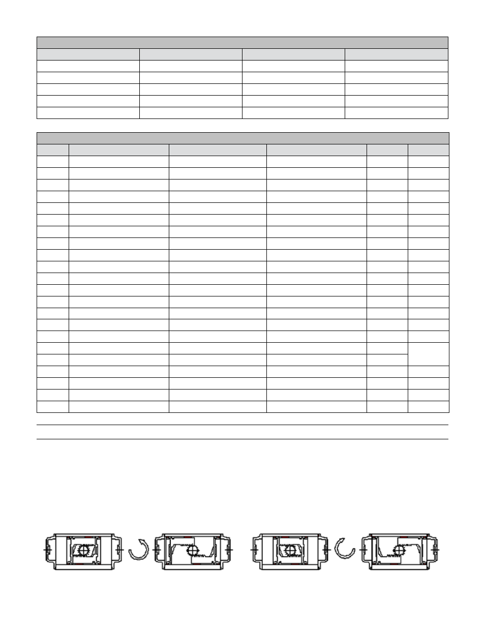
Assembly Possibilities - Top View
Counterclockwise Rotation (Standard)
Clockwise Rotation (Reversed Pistons)
Closed
Open
Open
Closed
A
B