Flue – MCZ Forma Wood 75 Dx - mod.2012 User Manual
Page 17
S
I
U
B
A
P
U
I
I
C
4
3
D
2
E
U
1
F
15
4-FLUE
Technical Dept. - All rights reserved - Reproduction is prohibited
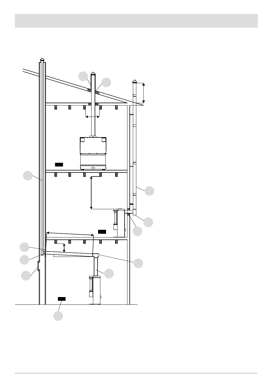
EXAMPLES OF CORRECT INSTALLATION
1. Installation of Ø200mm flue with hole for the passage
of the pipe increased by:
minimum 100 mm around the tube if next to non
flammable parts such as cement, brick, etc.; or
minimum 400mm around the pipe (or as required by data
tags) if next to flammable parts such as wood etc.
In both cases, install suitable insulation between the flue
and the ceiling.
Always check and respect the data tags on the flue,
in particular the minimum safety distances from
combustible materials.
The previous rules also apply for holes made in walls.
2. Old flue, minimum tube Ø200mm with the inclusion of
an external access door for chimney cleaning.
3. External flue made of insulated stainless steel tubes,
i.e. with double walls minimum Ø200mm: all securely
mounted to the wall. With wind-proof chimney. See fig.
7 type A.
4. Ducting system using T fittings that allow easy access
for cleaning without having to remove the pipes.
NOTE: in the event of hydro fireplaces maintain the
safety distance indications with the included insulation
indications.
FIGURE 11
u = insulating
i = inspection cap
s = inspection access panel
P = air inlet
a = minimum 40 mm
b = maximum 2 m
c = minimum 3°
d = minimum 400 mm
e = hole diameter
f = see fig.2-3-4-5-6