Fig.2 fig.1, Specifications, Assembly instructions – Sealey SUPERSTART520 User Manual
Page 2
2. specIFIcatIONs
MODeL NO: . . . . . . . . . . . . . . . . . . . . . . . . . . . . . . . . . . . . . . . . . superstart520.V5. . . . . . . . . . . . . . superstart620.V5
Input. . . . . . . . . . . . . . . . . . . . . . . . . . . . . . . . . . . . . . . . . . . . . . . . . . . . . . . . . . . . . . 230V. . . . . . . . . . . . . . . . . . . . . . . . . . . .230V
output . . . . . . . . . . . . . . . . . . . . . . . . . . . . . . . . . . . . . . . . . . . . . . . . . . . . . . . . . 12V/24V. . . . . . . . . . . . . . . . . . . . . . . . . 12V/24V
output 12V charge Peak (En) . . . . . . . . . . . . . . . . . . . . . . . . . . . . . . . . . . . . . 75A (50A). . . . . . . . . . . . . . . . . . . . . . . . 90A (70A)
output 24V charge Peak (En) . . . . . . . . . . . . . . . . . . . . . . . . . . . . . . . . . . . . . 75A (50A). . . . . . . . . . . . . . . . . . . . . . . . 90A (70A)
output 12V start Peak (En) . . . . . . . . . . . . . . . . . . . . . . . . . . . . . . . . . . . . . 450A (300A). . . . . . . . . . . . . . . . . . . . . . 570A (360A)
output 24V start Peak (En) . . . . . . . . . . . . . . . . . . . . . . . . . . . . . . . . . . . . . 450A (300A). . . . . . . . . . . . . . . . . . . . . . 570A (360A)
Input-charge . . . . . . . . . . . . . . . . . . . . . . . . . . . . . . . . . . . . . . . . . . . . . . . . . . . . . 6A/12A. . . . . . . . . . . . . . . . . . . . . . . . . . 9A/16A
Input-start . . . . . . . . . . . . . . . . . . . . . . . . . . . . . . . . . . . . . . . . . . . . . . . . . . . . . . . . . . 30A. . . . . . . . . . . . . . . . . . . . . . . . . . . . . 30A
fuse ref. (quantity) . . . . . . . . . . . . . . . . . . . . . . . . . . . . . . . . . . . . . . . . .120/121003 (2). . . . . . . . . . . . . . . . . . . .120/121003 (2)
Pack of 20 fuses . . . . . . . . . . . . . . . . . . . . . . . . . . . . . . . . . . . . . . . . . . . . . . 120/802029. . . . . . . . . . . . . . . . . . . . . . 120/802029
3. asseMBLY INstructIONs
1.3. geNeraL saFetY INstructIONs
familiarise yourself with the application, limitations and potential hazards relating to starter/chargers. Also refer to the vehicle
manufacturer’s hand book. If In AnY DouBt consuLt An ELEctrIcIAn.
only use recommended attachments and parts. to use non-recommended items may be dangerous and will invalidate your warranty.
use the starter/charger in the upright position only and ensure it is placed on a stable surface which will adequately support the weight.
Ensure the starter/charger is ‘off’ and disconnected from the mains supply before handling the power clamps.
Ensure the starter/charger is ‘off’ and disconnected from the mains supply before attaching/detaching the power clamps to/from the battery.
Keep tools and other items away from the engine and ensure you can see the battery and moving parts of the engine clearly.
Ensure the voltage on the starter/charger is set to the same voltage as the battery.
If battery has caps to access the battery fluid, remove the caps and check the fluid level before connecting the power clamps. If
necessary top-up the battery with distilled water by referring to the battery manufacturer’s instructions (apply the personal safety
precautions described in para. 1.3).
the cables may become hot with excessive use. If so, allow a few minutes for them to cool down before attempting to re-use.
If the starter/charger receives a sharp knock or blow the unit must be checked by a qualified service agent before using.
If the battery terminals are corroded or dirty clean them before attaching the power clamps.
Keep children and unauthorised persons away from the work area.
Do not dis-assemble the starter/charger for any reason. the starter/charger must only be checked by qualified service personnel.
Do not try to charge a non-rechargeable battery.
Do not try to start engine, or to charge battery, if battery is frozen.
WarNINg! to prevent the risk of sparking, short circuit and possible explosion Do not drop metal tools in the battery area, or allow
them to touch the battery terminals.
Do not allow power clamps to touch each other or to make contact with any metallic parts of the vehicle.
Do not cross connect power leads from starter/charger to battery. Ensure positive (+) (rED) is to positive and negative (-) BLAcK is
to negative.
If symbols cannot be distinguished, remember that the negative terminal is the one directly connected to the vehicle bodywork.
Do not pull the cables or clamps from the battery terminals and Do not remove power clamps while the starter/charger is ‘on’.
Do not use the starter/charger outdoors, or in damp or wet locations and Do not operate within the vicinity of flammable liquids or gases.
Do not use starter/charger inside vehicle or inside engine compartment. Ensure there is sufficient ventilation and do not cover or
obstruct starter/charger ventilation louvres.
Do not use this product to perform a task for which it is not designed.
WarNINg! simultaneous charging of batteries is possible but must be done with great caution by a qualified person. contact your
sealey dealer for information and accessories. Do not charge in series two batteries of differing type, capacity, or levels of discharge.
WarNINg! If a fuse blows, ensure it is replaced with an identical fuse type and rating.
When not in use, store the starter/charger carefully in a safe, dry, childproof location.
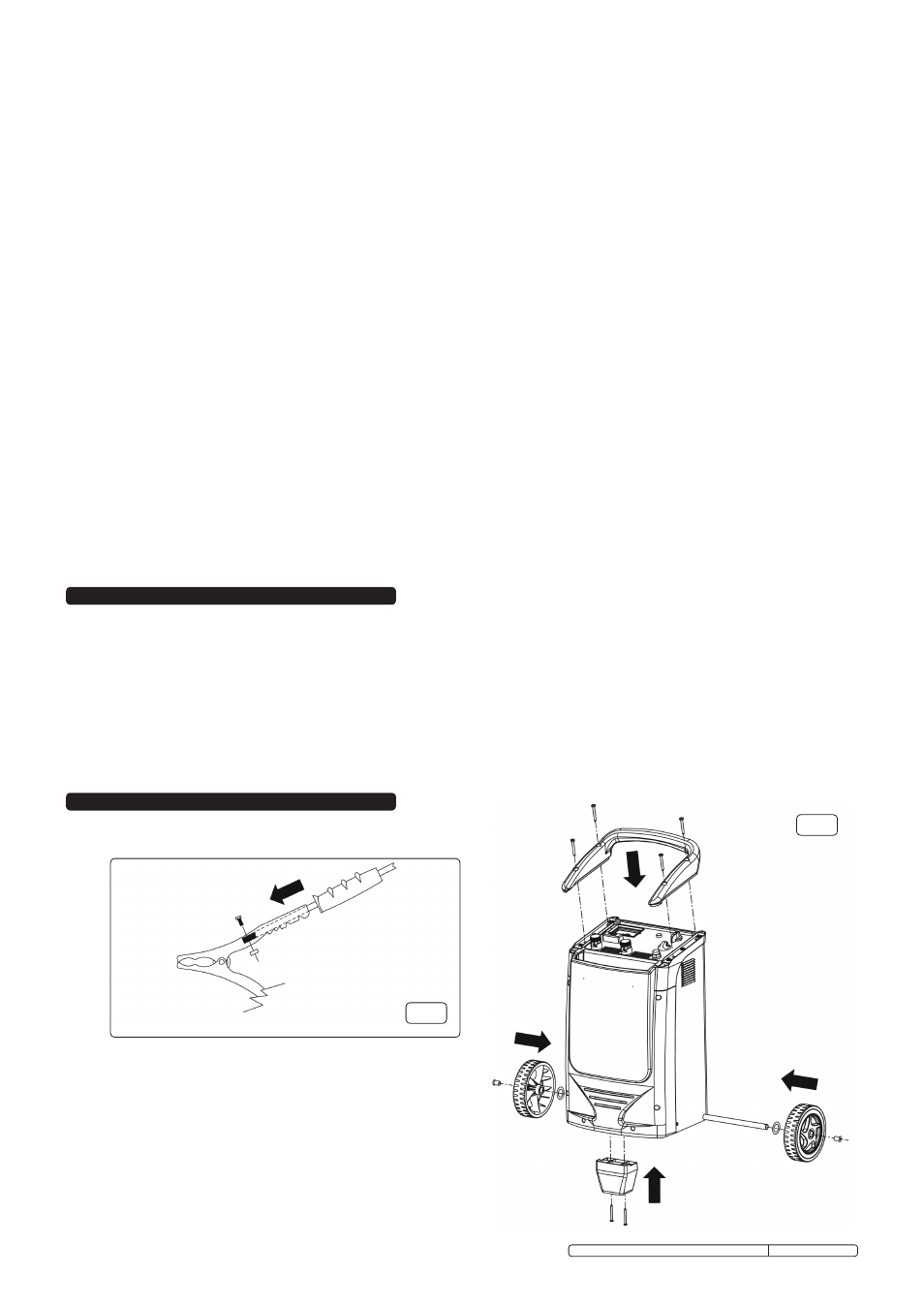
3.1
geNeraL asseMBLY. Assemble the handle and foot to the main
casing using the fittings provided as indicated in fig.2.
3.1.1 slide the axle through the casing at the bottom back corner.
3.1.2 Attach the wheels using the fittings provided as indicated in fig.2.
3.2
BatterY cLaMps. (see fig.1)
3.2.1 Assemble the clamp with the red handle to the movable cable.
3.2.2 Assemble the clamp with the black handle to the fixed cable which
comes directly out of the front of the battery charger.
fig.2
fig.1
Original Language Version
suPErstArt520.V5, suPErstArt620.V5 Issue: 2 - 16/03/10