Fig.2 fig.1 – Sealey PC200SD User Manual
Page 2
PC200SD.V3 Issue No.2 16/10/09
Original Language Version
2. cONTeNTS AND SpecIFIcATIONS
2.1
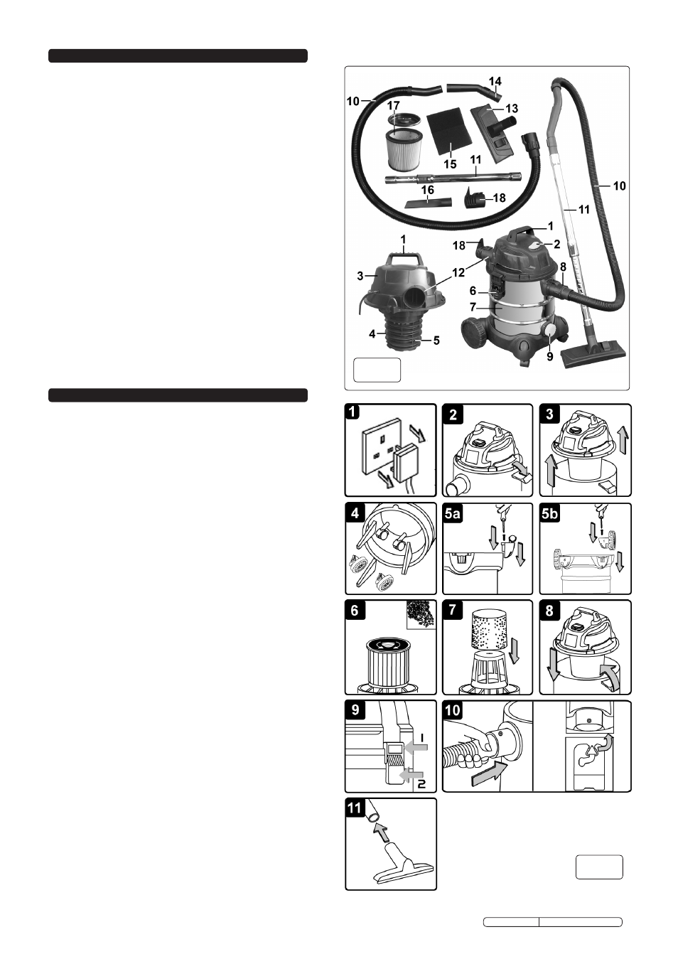
carton content
2.1.1
Carefully unpack the carton.
2.1.2
locate the two side clasps (fig.1.6) which hold the top
section (fig.1.3) in place.
2.1.3
undo the clasps, remove the power head and take out the
items in the container.
2.1.4
Check and identify each component as listed below. If anything
is missing or damaged please contact your supplier immediately.
2.2
Specification
motor: ..............................................................................230V 1250W
max. Vacuum Pressure .........................................................140mbar
Air flow ...................................................................................120m³/h
Container .....................................................................................20ltr
Weight ............................................................................................5kg
Vac Accessories Ø: ....................................................................35mm
filter (See Sect.9 ‘Consumables’) - Dry: ....... locking Cartridge filter
filter (See Sect.9 ‘Consumables’) - Wet: ...................................foam
3. ASSemBLY
3.1
ensure the mains plug is disconnected. (fig.2.1)
3.2
undo clasps. (fig.2.2)
3.3
lift off the power head assembly. (fig.2.3)
3.4
remove contents from inside the container. (fig.2.4)
3.5a turn the drum upside down and insert the castor
assembly mouldings into the slots in the base either
side of the blue drain cap. ensure they are pushed all
the way in and fix them with the self tapping screws
provided. (fig.2.5a) Do not overtighten.
3.5b the wheel assembly mouldings are marked 1 and 2.
Insert the wheel assembly mouldings into the two
remaining slots in the base ensuring that the number
on each moulding matches the number to be found on
the base. ensure they are pushed all the way in and
fix them with the self tapping screws provided
(fig.2.5b) Do not overtighten.
3.6
for dry vacuum cleaning use the locking cartridge
filter supplied and with the raised rim uppermost fit the
cartridge filter tube down over the filter basket and
push fully home. Place the locking disc onto the top of
the filter and turn the locking bar until the latch drops
into the slot in the top of the filter basket. Continue
turning until the filter is fully locked down. (fig.2.6)
3.7
for wet vacuum cleaning fit the supplied foam filter.
(fig.2.7)
NOTe: Do not operate the cleaner without a cartridge
filter fitted as this will damage the machine and invalidate
your warranty.
3.8
replace the power head assembly onto the drum
ensuring that the blue on/off switch is above the
vacuum hose connector. (fig.2.8)
3.9
Align the ridges on the rim of the power head with the
two side clasps. Place the upper part of each clasp
over the ridges and snap the clasps into place by
pressing on the lower part of each clasp in turn. (fig.2.9)
3.10 Align the arrow symbol on the large end of the
vacuum hose with the pin on the front inlet of the
drum. Push the fitting into the inlet and lock in place
by turning the fitting clockwise. (fig.2.10)
3.11 Choose the desired nozzle and push it onto the
telescopic suction tube. (fig.2.11)
Item Description
1 Handle
2 oN/off switch
3 top section
4 filter basket
5 Safety float valve
6 Clasp
7 Stainless Steel drum
8 Vacuum hose connection
9 Drain Cap
10 flexible vacuum hose
Item Description
11 telescopic suction tube
12 Blow connection
13 Combination nozzle
14 Air regulator handle
15 foam filter
16 Crevice nozzle
17 locking Cartridge filter
(fitted as standard)
18 Noise muffler
fig.2
fig.1