Ppc 25 installation instructions, cont’d – Extron electronic Priority Page Controller PPC 25 User Manual
Page 2
PPC 25 Priority Page Sensor • Installation Instructions
2
PPC 25 Installation Instructions, cont’d
Extron Electronics, USA
1230 South Lewis Street
Anaheim, CA 92805
800.633.9876 714.491.1500
FAX 714.491.1517
Extron Electronics, Europe
Beeldschermweg 6C
3821 AH Amersfoort, The Netherlands
+800.3987.6673 +31.33.453.4040
FAX +31.33.453.4050
Extron Electronics, Japan
Kyodo Building, 16 Ichibancho
Chiyoda-ku, Tokyo 102-0082
Japan
+81.3.3511.7655 FAX +81.3.3511.7656
Extron Electronics, Asia
135 Joo Seng Rd. #04-01
PM Industrial Bldg., Singapore 368363
+800.7339.8766 +65.6383.4400
FAX +65.6383.4664
www.extron.com
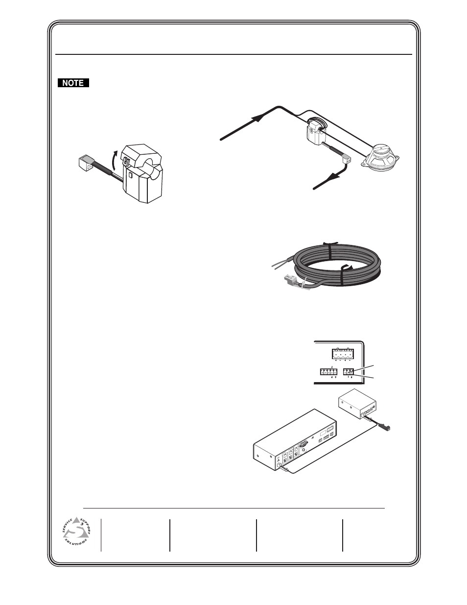
Installation Procedure
Follow all local fire and safety code requirements for installation and anchoring. Install the PPC 25
Sensor in a UL-compliant junction box with a cover to meet plenum rating requirements.
1
. Open the top of the Priority Page Sensor.
2
. Loop either one of the speaker wire leads around the top (open) part of the Sensor, and connect it to the speaker
as shown above. Connect the other speaker wire directly to the speaker. Polarity need not be observed.
• For a 25V or 70V system — wrap 5 to 8 loops.
• For a 4/8 ohm system — wrap 2 to 4 loops.
3
. Close and latch the top of the Priority Page Sensor.
4
. Cut an 18" section from the unterminated end of the supplied
blue sensor cable for use in step 8 below.
5
. Strip 3/16” of insulation from each conductor on the bare wire
end of the blue sensor cable. Do not tin the leads.
6
. Connect the stripped leads to the 2-pole captive screw connector
on the Priority Page Sensor. Polarity need not be observed.
7
. Route the connector end to the PPC 25 Controller, and plug it into the PAGING SENSOR receptacle.
8
. Connect the 18” 2-conductor cable (from step 4) from the RELAY OUT port on the PPC 25 Controller to the mute
control input port on the audio amp or switcher to be muted during a PA system announcement. Polarity need
not be observed.
When integrating the PPC 25 into a PoleVault System:
1
. Connect the 18” cable (from step 4 above) from the RELAY OUT
port on the PPC 25 Controller to the MUTE and GROUND pins
on the PoleVault PVS 204SA VOL/MUTE port. Polarity need not
be observed.
2
. Use the included cable assembly (PN 27-576-01LF) to power the
PPC 25 from the PVS 204SA power supply. The PPC 25 must be
mounted near the PVS 204SA and its power supply.
Testing and Adjustment Procedure
To test that the classroom audio is muted when a
PA system announcment (page) occurs:
1
. Turn the classroom audio on.
2
. Speak into the PA system microphone. The classroom
audio should be muted while the PA system page occurs, and be restored when the page ends.
3
. If the PPC 25 fails to mute the classroom audio during a page, turn the SENSITIVITY adjustment clockwise.
4
. If classroom audio is muted without a page occurring, turn the SENSITIVITY adjustment counterclockwise.
Ceiling Mounted
Paging Speaker
Priority
Page
Sensor
From
PA system
To Priority
Page Controller
Blue
Sensor
Cable
PO
WE
R
C
NO
PAG
ING
RE
LAY
DE
LAY
SE
NS
ITIV
ITY
12V
0.2
A
MA
X
ON
1
2
L
R
AU
X/M
IX
IN
DO
NO
T G
RO
UN
D
OR
SH
OR
T
SP
EA
KE
R O
UT
PU
TS
!
1B
1A
I
N
P
U
T
S
O
U
T
P
U
T
S
2B
2A
3B
3A
RS
-23
2 M
LC
/IR
DC
VO
L
4/8
Oh
ms
AM
PL
IFIE
D O
UT
PU
TS
VO
L/M
UT
E
Tx
A
B
C
Rx
IR
12V
10V
PO
WE
R
12V
3A
M
AX
US
LIS
TED
17
TT
AU
DIO
/VID
EO
AP
PAR
ATU
S
®
RG
B
VIDEO
RGB
VID
EO
To Power Supply
Extron
PPC 25
Priority Page
Controller
Extron
PVS 204SA
Twisted Pair
Switcher
Extron
PVS 204SA
Rear Panel
L
R
RS-232 MLC/IR
DC VOL
4/8
Ohms
AMPLIFIED OUTPUTS
VOL/MUTE
Tx
A B C
Rx IR
12V
10V
Mute (center)
Ground (right)