Assembly, Required tools, Stand assembly – Elektra Beckum TKHS 315 C User Manual
Page 8: On/off switch installation, Installing the dust collection gear, English
20
ENGLISH
(55) Small edge:
− for cutting thin stock;
− when the saw blade is tilted.
(56) Wide edge:
− for cutting thick stock
A
Danger!
Modifications of the saw or the
use of parts not tested and approved
by the equipment manufacturer can
lead to unforeseen damage during
operation!
− Assemble the saw in strict
accordance with these instruc-
tions.
− Use only the parts supplied as
standard delivery.
− Do not change any parts.
Only if you follow the instructions exactly
does the saw conform to the safety regu-
lations and can be safely operated.
If you also observe the following notes,
the assembly will cause no problems:
• Read the instructions for each step
before executing it.
• Lay out the parts required for each
assembly step.
Required tools
− Two 10 mm wrenches
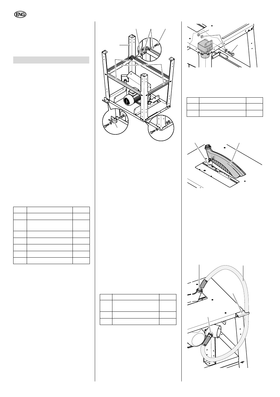
Stand assembly
1.
Place table panel, motor facing up,
on a stable support.
A
Caution!
Saw blade and riving knife
must not rest on the support! To pre-
vent damage to the saw or support,
the table panel should be placed onto
two sawhorses.
2.
Attaching the four legs (57) to the
inside of the table panel's corners:
− Put hexagon head screws (58)
with washers (59) fitted through
from the outside;
− from the inside put on washers
(59) and screw on hexagon nuts
(60) – do not fully tighten yet.
3.
At the location indicated by an arrow
attach the hose carrier (61), with the
opening to the rear, to the saw table.
4.
Fit long stanchions (62) between the
side legs, short stanchions (63)
between the front and rear legs:
− the wide sides of the stanchions
face the table panel;
− the nibs and recesses must fit
into each other;
− Put hexagon head screws with
washers fitted through from the
outside;
− from the inside put on washers
and screw on hexagon nuts – do
not fully tighten yet.
5.
Screwing up the stanchions with
each other:
− Put hexagon head screws with
washers fitted through from the
saw table's top side;
− from the underside put on wash-
ers and screw on hexagon nuts –
do not fully tighten yet.
− With the help of another person,
turn the saw over and stand it on
a level floor.
6.
Tighten all hexagon head screws
and hexagon nuts of the saw stand.
ON/OFF switch installation
1.
Remove the transport lock of the
switch and attach the switch plate
from the inside to the edge of the
saw table:
− Put hexagon head screws (64)
with washers (65) fitted through
from the outside;
− from inside put on washers (65)
and screw on hexagon nuts (66).
A
Caution!
Make sure the cable does not
run over sharp edges and is not bent.
Installing the dust collection gear
1.
Raise saw blade fully.
2.
Install blade guard (67) on the riving
knife (68).
3.
Push one end of the suction hose
(69) on the blade guard's suction
port (70).
4.
Fit other end of the suction hose to
the dust extraction port (71) on the
chipcase.
5.
Hook the suction hose into the hose
carrier (72).
6.
Connect the saw's dust extraction
port at the chip case to a suitable
dust collector (see "Dust collector" in
chapter "Operation").
7.
Assembly
Item
Description
Qty.
Leg
4
Hexagon head screw
M6 x 16
28
Washer 6.4
56
Hexagon nut M6
28
Hose carrier
1
Stanchion, long
2
Stanchion, short
2
Item
Description
Qty.
Hexagon head screw
M6 x 16
2
Washer 6.4
4
Hexagon nut M6
2
63
57
62
58
59
61
60
Item
Description
Qty.
Blade guard
1
Suction hose
1
64
65
66
67
68
69
70
71
72