Gas cooktop installation instructions – Electrolux EW30GC55G User Manual
Page 8
GAS COOKTOP INSTALLATION INSTRUCTIONS
(For 30" & 36" Models)
8
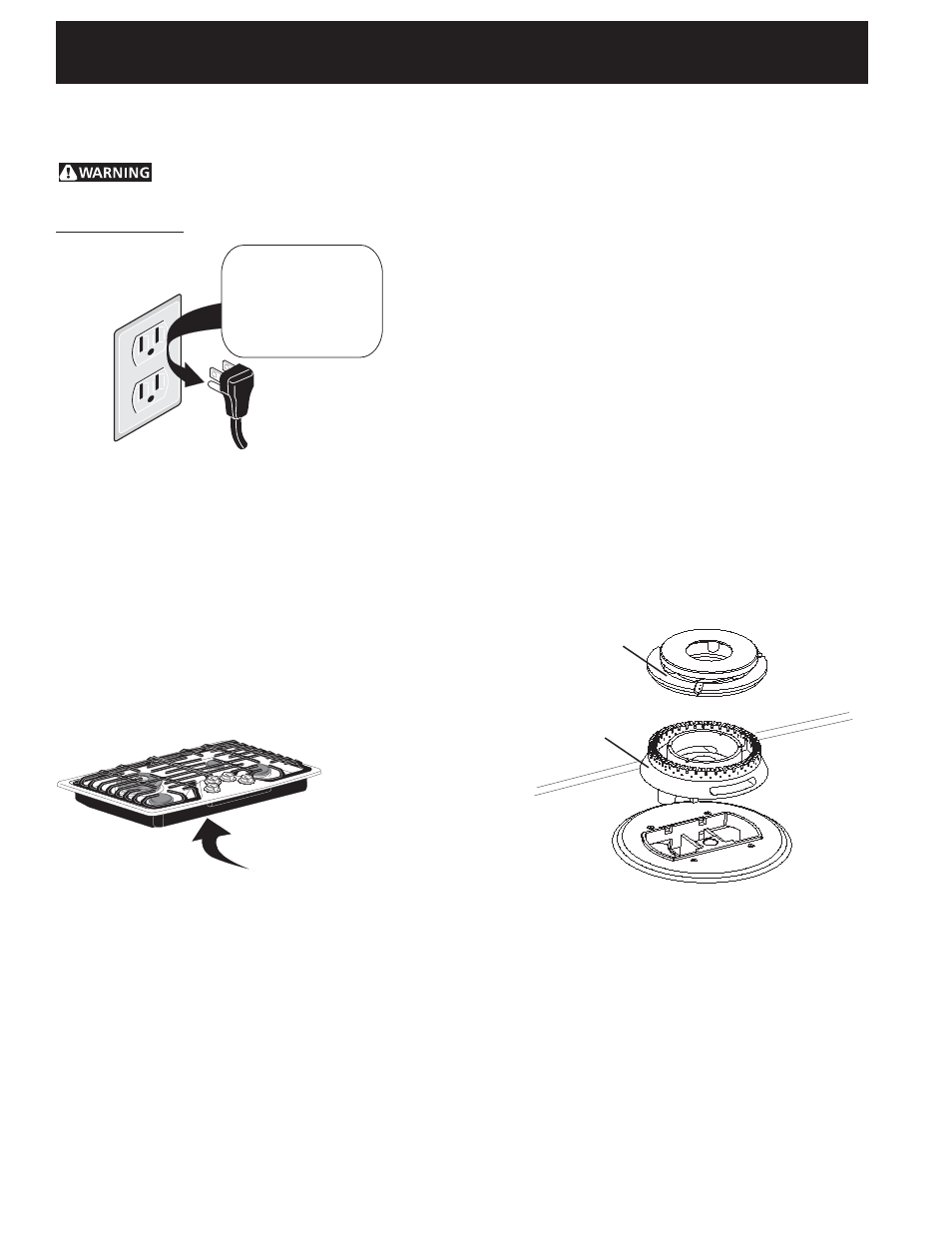
Figure 11
Check Operation
Refer to the Use and Care Guide packaged with the
cooktop for operating instructions and for care and
cleaning of your cooktop.
Do not touch the burners. They may be hot enough to
cause burns.
1.
Install Burner Caps and Triple burner head
This cooktop is equipped with sealed burners.
A. Unpack the burner grates.
B.
Regular Burners: Burner heads and burner caps
are already on the surface. Remove all tapes
from burner caps and verify if they are correctly
place on the burner heads.
C. Triple Burner (if equipped): Remove all tapes
from burner cap. Remove the burner cap and
head. Remove and discard the packaging
material. Replace head and cap on the triple
burner. Be careful not to damage the
electrode while placing the head over the
orifice. Make sure electrode fits correctly into
slot in burner head (see Figure 11).
D. Be sure that all the burner caps and the triple
burner head are correctly placed BEFORE using
your cooktop.
Do not, under any circumstances, cut or remove the
third (ground) prong from the power cord.
Disconnect electrical supply cord from
wall receptacle before servicing cooktop.
Model and Serial Number Location
The serial plate is located on the underside of the
cooktop (see Figure 10).
When ordering parts for or making inquires about your
range, always be sure to include the model and serial
numbers and a lot number or letter from the serial plate
of your cooktop.
Your serial plate also tells you the rating of the burners,
the type of fuel and the pressure the cooktop was
adjusted for when it left the factory.
NOTE: There are no burner adjustments necessary on
this cooktop.
Preferred Method
Grounding type
wall receptacle
Do not, under any
circumstances, cut,
remove, or bypass
the grounding
prong.
Power supply cord with 3-
prong grounding plug.
Figure 9
Serial plate is
located under the
burner box.
Figure 10
Burner Cap
Burner Head