Figure 2-6. jumper selection label -10, World class 3000, Instruction bulletin – Emerson WORLD CLASS 3000 User Manual
Page 22
Instruction Bulletin
106-300NE Rev. 3.4
May 2000
2-10 Installation
Rosemount Analytical Inc. A Division of Emerson Process Management
World Class 3000
ALWAYS DISCONNECT LINE VOLTAGE
FROM HEATER POWER SUPPLY AND
ANALOG ELECTRONICS (IF USED)
BEFORE CHANGING JUMPERS.
JUMPER
CONFIGURATIONS
LINE VOLTAGE
SELECTION
JUMPER
(INSTALL)
JUMPER
(INSTALL)
HEATER
POWER
JUMPER
100/120 V.A.C.
220/240 V.A.C.
JM4, JM1
JM5
REMOTE
*ON
REMOVE JM2
INSTALL JM2
ELECTRONICS
SELECTION
JUMPER
PROBE HEATER
VOLTAGE SELECTION
INSTALL JM3, JM6
REMOVE JM3, JM6
*ANALOG (EXISTING)
DIGITAL
(NEXT GENERATION)
*WORLD CLASS PROBE
(44V)
JM7
JM8
218 PROBE (115V)
DENOTES JUMPERS THAT MUST BE INSTALLED WHEN USING THE WORLD CLASS 3000 OXYGEN ANALYZER
PROBE AND THE HPS 3000 HEATER POWER SUPPLY WITH EXISTING ANALOG, MODEL 218A, AND TC 2000
ELECTRONICS.
*
1
2
NOTES:
100 V.A.C. OPERATION REQUIRES TRANSFORMER PART NUMBER 1M02961G02.
HEATER POWER IS ALSO REFERRED TO AS LINE VOLTAGE RELAY.
1
2
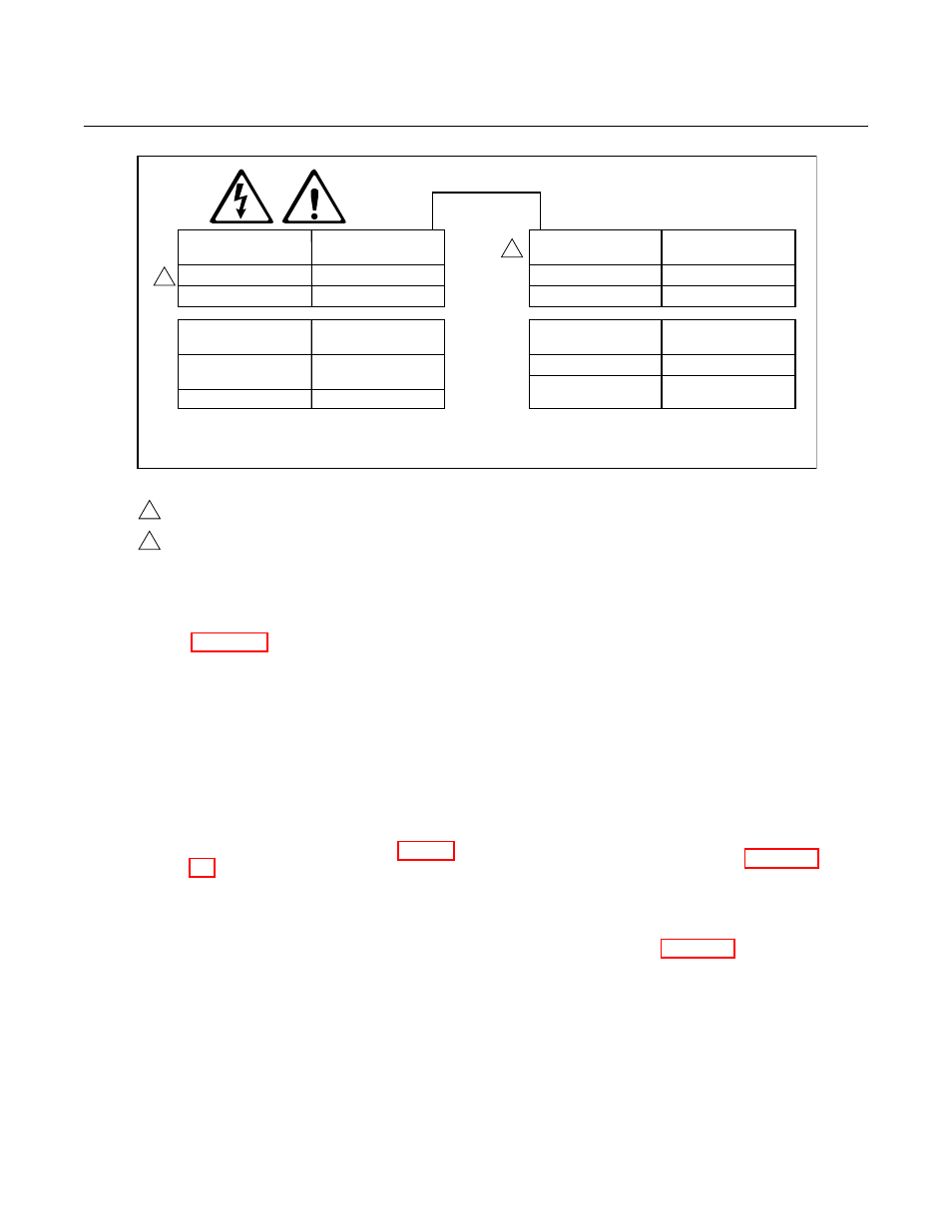
Figure 2-6. Jumper Selection Label
NOTE
Refer to Figure 2-7 for HPS unit fuse
locations and specifications.
NOTE
Before supplying power to the heater
power supply, verify that jumpers JM2,
JM3, JM6, and JM7 are installed.
2. Power Input: 120, 220 or 240 Vac. For
120 Vac usage, install jumpers JM4
and JM1. For 220 or 240 Vac usage,
install jumper JM5 (See label, Figure
2-6).
For 100 Vac usage, the heater power
supply is factory-supplied with a differ-
ent transformer. When using the HPS
with 100 Vac transformer, install
jumpers JM1 and JM4.
3. The power cable should comply with all
applicable codes and safety regula-
tions in the user's country and should
not be smaller than 16 gauge, 3 amp.
NOTE
"ANALOG" under ELECTRONICS SE-
LECTION on the label refers to Models
218, 225, TC200, and Model 218A elec-
tronics.
4. Before supplying power to the heater
power supply, verify that the jumpers
on the mother board, Figure 2-7, are
properly configured. Jumpers JM2,
JM3, JM6, and JM7 should be in-
stalled. Additionally, make sure that the
proper jumper for your line voltage is
installed, Figure 2-6.