Ash disposal – England's Stove Works Room Heater 50-TFP12G User Manual
Page 17
17
ASH DISPOSAL
Regularly inspect the ash build-up in your unit and remove as necessary. Ashes can be removed
from the unit by shoveling them off the firebrick. This unit has an ash drawer plate (see Illustration 4)
that can be removed from the stove; once removed, the ashes can be raked through the opening and
into the ash pan.
Caution: The ash drawer plate can be extremely hot!! Never remove red-hot ashes from the
appliance; allow ashes to cool before dropping into the ash pan. Ashes should be placed in a metal
container with an airtight lid. The ashes should be placed on a noncombustible surface and
completely away from any combustible materials. The ashes should remain in the airtight container
until they have completely cooled.
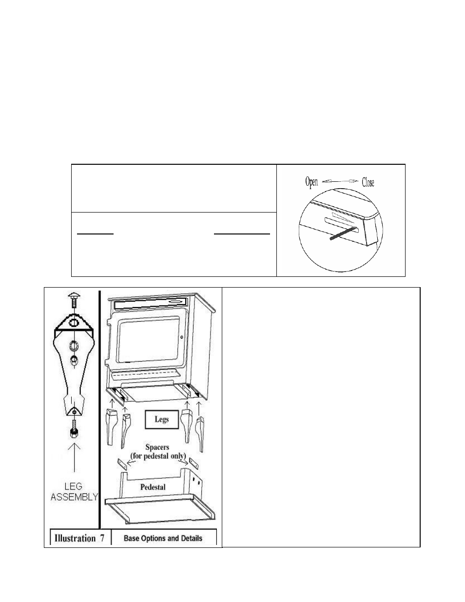
DIRECTIONS FOR INSTALLATION OF
LEGS OR PEDESTAL:
(Stove must be cooled and all ashes cleaned out)
*
Remove bricks, disconnect flue, and turn stove on its
back.
*
If you are replacing existing legs or pedestal,
disconnect the existing legs or pedestal.
To install legs:
1. Each leg will fit into a pre-made slot on each corner
of the bottom of the unit.
2. A 3/8” x 1-1/2” Carriage Bolt and matching nut is
supplied with each leg. Fit a leg into a slot, and
match the hole on the leg with the hole in the slot.
Attach the legs one at a time, using the supplied
bolts and nuts. Tighten securely.
To install pedestal:
1. Place spacers (provided) between the slots on the
unit and the pedestal base (one spacer will fit on
each side of the pedestal). Match the four holes in
the pedestal (2 on each side) with the holes in the
spacers and slots on the unit.
2. Use the four 3/8” x 1-1/2” Carriage Bolts and nuts
(provided) to attach the pedestal to the base of the
stove. Tighten securely.
*
After attaching the legs or pedestal, turn unit upright,
reconnect flue and replace bricks according to
manual.
CONTROL SETTINGS
Burn Rate
Inlet
Air
Setting
Low
Fully
Closed
Med.
Low
¼
Open
Med.
High
¾
Open
High
Fully
Open
Illustration 6 – Air Inlet Control