Example 8: adjust the input audio gain, Example 8: adjust the input audio gain -20, Preliminar y – Extron electronic MVX 88 Series User Manual
Page 38: Operation, cont’d
Operation, cont’d
MVX 44 / 48 / 84 / 88 VGA Matrix Switchers • Operation
3-20
PRELIMINAR
Y
5
.
Press and release the Audio Setup button to save the level value in memory
and to exit Audio Setup mode. The Audio Setup LED turns off.
N
• After approximately 30 seconds of front panel inactivity, the switcher saves
the most recent input gain or attenuation levels and exits
Audio Setup
mode.
• There is one audio gain or attenuation setting per input. The setting is
shared by the left and right audio inputs.
• The input audio gain or attenuation settings are stored in non-volatile
memory. When power is removed and restored, the audio level settings are
retained.
Example 8: Adjust the input audio gain
The following steps show an example in which an input audio level is viewed and
adjusted. The example shows the front panel indications that result from your
actions.
1
.
Press and hold the Audio Setup (I/O) button for approximately 2 seconds
(figure 3-31) until the Audio Setup LED lights.
AUDIO SETUP
AUDIO SETUP
The LED
lights to indicate Audio Setup mode.
Release the Audio Setup button.
2 seconds
Press and
hold the button.
Figure 3-31 — Select Audio Setup mode
2
.
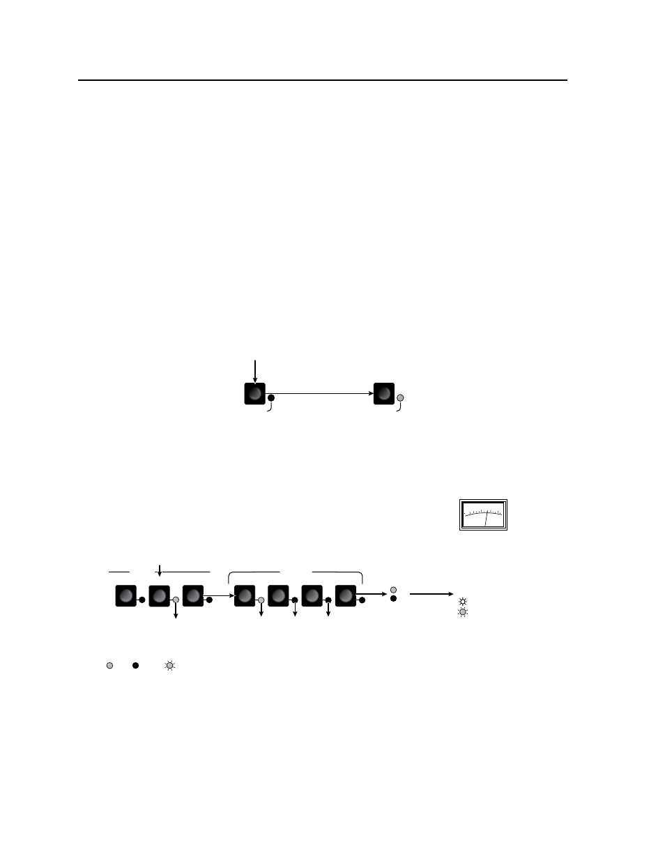
Press and release the Input 5 button (figure 3-32).
VU
3
3
0
+
6
10
2
1
4
3
OUTPUTS
6
5
4
INPUTS
+dB
-dB
The Output 1, Output 2, and Output 3
LEDs display input 5's audio level range.
The +dB LED indicates
a gain (positive) level.
The power LED lights
steadily or blinks off only
occasionally to indicate
that the adjusted level is
too high.
A VU meter connected
to output 1 indicates
that the adjusted level
is approximately +9 dB
above the –10 dBV
internal level.
In this example, the LEDs indicate gain in the +6 dB to +10 dB range.
Press and release the Input 5 button.
The Input 5 LED lights to
indicate that input 5 is selected.
= lit, = unlit,
= blinking LED
Figure 3-32 — Select an input
If the +dB and –dB LED are both lit they indicate an input gain of 0 dB.
Otherwise, you can determine the exact gain or attenuation using the
following procedure: