Theory of operation, Power supply considerations, Setting the module address – Linx Technologies FCTN-RLY4-xxx-2 User Manual
Page 2
Page 3
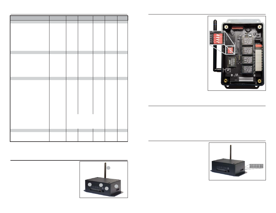
THEORY OF OPERATION
The FCTN-RLY4-***-2 module
combines the popular Linx LR
Series receiver with a decoder IC
and four relays that are capable of
switching a variety of AC or DC
loads. The Relay Function Module
is designed to receive a wireless
signal transmitted from a
compatible Linx RF module or pre-
certified OEM transmitter. When
transmitted data is received, the
data is presented to the decoder.
The decoder detects the logic states
of the DIP switch address lines, and
if they match the address settings of
the encoder, the decoder’s outputs
are set to replicate the state of the
encoder’s data lines. Figure 3
shows the inside of the module. The
four position DIP switch, S2, allows
each relay to be set to latched (LAT)
or momentary (MOM) operation.
POWER SUPPLY CONSIDERATIONS
The module should be powered from a DC source that is free of noise and high
ripple. The best results are normally obtained using a battery or high quality AC
wall adapter capable of providing the supply currents indicated in the Electrical
Specifications section. Two supply connection options are provided: black
(ground) and red (+) quick-connect terminals or a barrel jack (for a 5.5mm shell,
2.1mm tip plug, tip +7 to 30VDC, shell ground). Only one connection should be
used at a time and proper supply polarity should be observed.
SETTING THE MODULE ADDRESS
The Relay Function Module provides
a total of 256 unique addreses to
avoid contention with other units or
to create unique relationships.
Address selection is made via eight
externally accessible DIP switches
as shown in the adjacent figure.
If the switch is on, the address line is
connected to ground, otherwise it is
floating. The transmitter’s address
must match exactly in order for the
units to communicate. Application
Note AN-00300 describes in detail how to set the address to match any of the
Holtek-based transmitters offered by Linx. This application note can be found in
the Support section of the Linx website, www.linxtechnologies.com.
Figure 3: Latched / Momentary DIP Switch
A7 = 1
A6 = 2
A5 =
3
A4 = 4
A
3
= 5
A2 = 6
A1 = 7
A0 =
8
OFF ON
Figure 4: Address DIP Switches
Page 2
1. Typical values at 12V and 25
°
C; Max and Min values are over the full voltage and temperature range.
2. Characterized, but not tested.
3. For BER of 10
-5
at 1,200bps.
Notes
ELECTRICAL SPECIFICATIONS
RELAY FUNCTION MODULE FEATURES
1. Antenna
2. DC Power Connector (7 to 30VDC)
3. “Quick-Connect” Alternate DC Input
4. Switched Device Connectors
5. Address Selector DIP Switches
1
2
5
4
3
Figure 2: Relay Module Features
Parameter
Designation
Min.
Typical
Max.
Units
Notes
POWER SUPPLY
Operating Voltage
V
CC
7.0
–
30.0
VDC
–
Supply Current
I
CC
RX Only
4.0
7.0
15.0
mA
1
RX and 1 Relay
16.0
36.0
65.0
mA
1
RX and 2 Relays
26.0
65.0
120.0
mA
1
RX and 3 Relays
35.0
95.0
175.0
mA
1
RX and 4 Relays
45.0
125.0
225.0
mA
1
RECEIVER SECTION
Receive Frequency Range
F
C
FCTN-RLY4-315
–
315
–
MHz
–
FCTN-RLY4-418
–
418
–
MHz
–
FCTN-RLY4-433
–
433.92
–
MHz
–
Center Frequency Accuracy
–
-50
–
+50
kHz
–
Receiver Sensitivity
–
-106
-112
-118
dBm
3
RELAY CHARACTERISTICS
Arrangement
–
SPST
Switched Power
–
–
–
480
watts
–
–
–
–
4000
VA
–
Relay Switching Voltage
–
0.0
–
30.0
VDC
–
–
0.0
–
300.0
VAC
–
Switched Device Current
–
0.6
–
7.0
A
–
Operate Time
–
–
10.0
–
mS
–
Release Time
–
–
5.0
–
mS
–
Life Expectancy
Mechanical
–
1x10
7
Operations
2
Electrical
–
1x10
5
@ 10A, 277VA
Contact Dielectric Strength
–
1000Vrms across contacts
(at sea level for 1 minute)
–
1750Vrms contact-to-coil
ENVIRONMENTAL
Operating Temperature Range
–
-40
–
+70
°
C
2
Storage Temperature Range
-45
–
+70
°
C
2