Theory of operation, Setting module address, Creating unique groups – Linx Technologies FCTN-WALL-xxx User Manual
Page 2: Equipment connection, Ac function module features, Electrical specifications
Parameter
Designation
Min.
Typical
Max.
Units
Notes
POWER SECTION
Operating Voltage
V
CC
–
110
120
VAC
–
Relay Rating
–
100
mA
2
Tungsten or Resistive load
–
–
15.0
A
1
Electronic Ballast
–
–
5.0
A
1
Power
–
–
1,800
W
1
Power
–
–
1
HP
1
Power
–
–
15
FLA
1
Relay Cycle Life
–
1x10
5
–
RECEIVER SECTION
Receive Frequency Range:
F
C
FCTN-WALL-315
–
315
–
MHz
–
FCTN-WALL-418
–
418
–
MHz
–
FCTN-WALL-433
–
433.92
–
MHz
–
Center Frequency Accuracy
–
-50
–
+50
kHz
–
Receiver Sensitivity
–
-106
-112
-118
dBm
–
Noise Bandwidth
N
3dB
–
280
–
kHz
1
ENVIRONMENTAL
Operating Temperature Range
–
-30
–
+50
°
C
1
Storage Temperature Range
-45
–
+85
°
C
1
THEORY OF OPERATION
The FCTN-WALL-*** module combines
the popular Linx LR Series receiver with a
decoder and high quality switching relay.
When transmitted data is received, the
data is presented to the decoder. The
decoder detects the logic states of the DIP
switch address lines, and if these match
the address settings of the encoder, the
decoder’s outputs are set to replicate the
state of the encoder’s inputs. In the AC
Function Module, the data lines are also
compared to the settings of four control dip
switches that determine which transmitter
buttons or data lines will be accepted. The
relationship is shown in the adjacent chart.
If the DIP switch labeled Button 1 is turned
on, then when data line D6 on the decoder
goes high, the AC Function Module will
activate and apply power to the output.
When line D7 goes high, the module will
turn off. As long as the other button
switches are turned off, the module will
ignore all of the other data lines. If multiple DIP switches are turned on, then the
module will be controlled by multiple buttons or data lines. For example, if
switches 1 and 2 are on, then lines D6 and D4 will switch the AC Function
Modules output on and lines D7 and D5 will turn it off.
SETTING MODULE ADDRESS
The AC Function Module provides a total of sixteen unique address settings.
Address selection is made via the bottom four DIP switches on the module. In
order for the encoded commands sent by the transmitter to be recognized, the
address settings of the transmitter and receiver must match exactly.
CREATING UNIQUE GROUPS
The four control DIP switches can be used to create distinct groups of AC
Function Modules that can all be operated by a single command unit. For
example, any number of AC Function Modules can be set to a single address
and be controlled by one of the button pairs (ON / OFF) on a command unit. You
can also set up different banks using up to sixteen AC Function Modules, each
set to a different address. Please read the Contention Considerations section
when using multiple transmitters in close proximity.
EQUIPMENT CONNECTION
Each AC Function Module is designed to switch AC loads of up to 1,800 watts.
Plug the AC Function Module in, then plug the equipment to be switched into the
receptacle on the face of the unit. More than one device can be connected with
the addition of a power strip; however, the total draw of all connected equipment
must never exceed the unit’s 1,800W rating.
DIP Switch
Data Lines
Button
Off
On
1
D7
D6
2
D5
D4
3
D3
D2
4
D1
D0
Page 3
Page 2
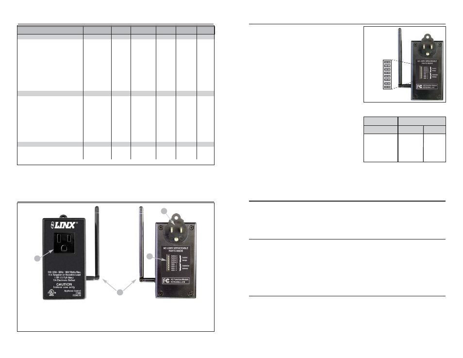
AC FUNCTION MODULE FEATURES
1. Up to 1,800 watts switched AC power outlet
2. Standard 3-prong plug can be used with wall outlet, power strip, or extension cord
3. Multi-position antenna for optimum reception
4. Control DIP Switches used to set address and command button
Figure 2: FCTN-WALL-*** Features
Figure 3: Module DIP Switches
ELECTRICAL SPECIFICATIONS
1. Characterized, but not tested.
2. Minumum relay load of any approved type
Notes
Table 1: FCTN-WALL-*** Specifications
1
2
3
4
OFF ON
A0 = Addr. 1
A1 = Addr. 2
A2 = Addr. 3
A3 = Addr. 4
Button 1
Button 2
Button 3
Button 4