Typical applications – Linx Technologies OTX-xxx-HH-KF-MS User Manual
Page 7
– –
– –
8
9
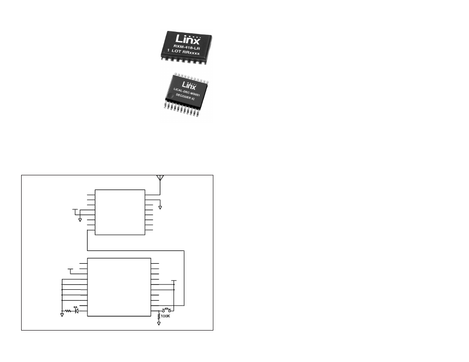
Typical Applications
The signal sent by the Keyfob transmitter can be
received by the LR Series receiver module or the LT
Series transceiver module. The receiver module is
connected directly to the MS Series decoder, which
decodes the transmitted signal.
When a button is pressed on the transmitter, a
corresponding line on the decoder goes high. This
can then be connected to external circuitry to perform
whatever function is required by the application.
The decoder must learn the transmitter’s address
before they can work together. This is done by taking
the LEARN line on the decoder high, typically with a
pushbutton. The MODE_IND line starts switching (if an LED is attached,
this causes it to flash) indicating that the decoder is in Learn Mode. Press
any of the buttons on the transmitter to initiate a transmission. Take the
LEARN line high again to exit Learn Mode and the system is ready for use.
Figure 10 shows a schematic for a typical application.
Figure 9: Linx RF Modules
The Keyfob is set to 9,600bps, so SEL_BAUD0 should be tied high and
SEL_BAUD1 tied low.
The decoder has several unique features, such as Latch Mode, Receiver
Control and TX_ID.
If the LATCH line is tied to V
CC
, the outputs go high on the first
transmission, then low on the second. It is shown tied low, so the outputs
are momentary (high for as long as a signal is received instructing the
decoder to make them high).
The RX_CNTL line can be connected to the PDN line of the receiver and
the decoder activates the receiver with a 10% duty cycle This greatly
reduces the average current consumption of the system. The adjacent
figure shows it tied to ground, but to use this feature, connect the RX_
CNTL line of the decoder directly to the receiver’s PDN line.
The TX_ID line outputs a number associated with the originating transmitter
/ encoder. Application Note AN-00156 shows how to use this feature.
Data guides for the modules, the MS encoder, and the MS decoder can be
found on the Linx Technologies website.
GND
GND
VCC
NC
1
NC
2
NC
3
GND
4
VCC
5
PDN
6
RSSI
7
DATA
8
NC
9
NC
10
NC
11
NC
12
NC
13
NC
14
GND
15
ANT
16
RXM-LR
220
D6
D7
SEL_BAUD0
SEL_BAUD1
GND
GND
LATCH
RX_CNTL
TX_ID
MODE_IND
D5
D4
D3
D2
VCC
VCC
D1
D0
DATA_IN
LEARN
1
2
3
4
5
6
7
8
9
10
11
12
13
14
15
16
17
18
19
20
LICAL-DEC-MS001
VCC
GND
GND
VCC
Figure 10: LR Receiver and MS Decoder Schematic