Using the development boards, Troubleshooting, The prototyping area – Linx Technologies MDEV-LICAL-HS User Manual
Page 5
–
–
–
–
4
5
Using the Development Boards
After unpacking the development system, attach an antenna to each
board, install the supplied 9V battery, and turn on the power switches. The
encoder and decoder are set at the factory and work straight out of the
box. To create a new operational setup, follow these steps:
1. On the decoder board, hold the LEARN button and press the
CREATE_KEY button to enter Create Key Mode. Release the LEARN
button and press the CREATE_KEY button ten times to generate the
KEY.
2. To use the infrared key transfer, press the IR_RXEN button on the
encoder board to activate the infrared receiver. Hold the IR sections of
the encoder and decoder boards close until the MODE_IND LEDs on
both boards light up.
3. To set Control Permissions, press the LEARN button on the decoder
board.
4. While the decoder’s MODE_IND LED is flashing, press each data line
button on the encoder that is needed for the application.
5. After all the desired data lines have been transmitted, press the
LEARN button again, or wait until the 15 second time-out occurs. The
permissions are now saved in the decoder.
6. Transmit with one or all the data lines held high to confirm that the learn
process was successful.
Troubleshooting
If the boards fail to work out of the box, then try the following:
• Check the battery to make sure it is not dead.
• Make sure that the baud rate switches are set the same on both
boards.
• Make sure that the antenna is connected and has the correct polarity
connector.
• Check to see if the PDN switch is on, placing the encoder and decoder
into Power Down Mode. In most cases, the encoder PDN switch
should be in the up position.
• Make sure that the Encryption Key is set correctly. This key is created
by the decoder and needs to be sent to the encoder before they will
communicate.
• Make sure that the Control Permissions are set correctly. If the encoder
is not set to use a particular line, then when the button on the encoder
board is pressed, the MODE_IND LED on the decoder board lights up,
but the data line LED does not light up.
If all of these appear to be in order, then call +1 800 736 6677 or email
[email protected] for technical support.
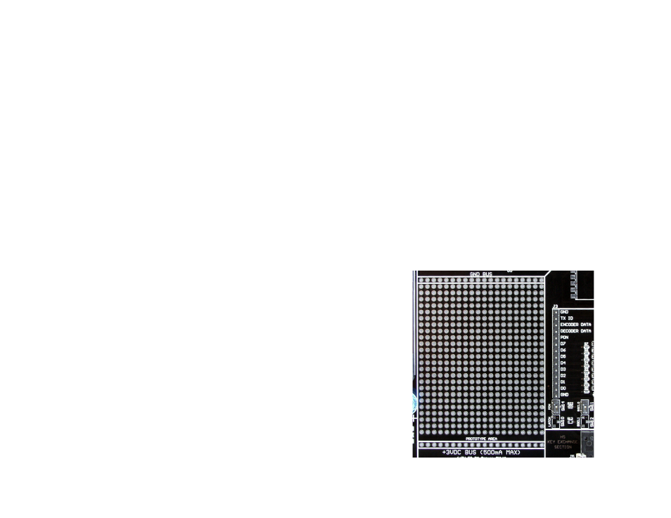
The Prototyping Area
The prototyping area is the same on both boards and contains a large
area of plated through holes so that external circuitry can be placed on
the board. This circuitry can be interfaced with the HS Series encoder or
decoder through the breakout header to the right. At the bottom of this
area is a row connected to the 3V power supply and at the top is a row
connected to ground.
All of the data lines are connected to a wire-wrap header to the right,
allowing easy access from the prototyping area. The DATA_IN, DATA_OUT,
and TX_ID lines are also available on the header, as well as the PDN lines
from the RF modules. This allows complete control of the entire system
from the prototyping area, giving the designer a great deal of flexibility in
using the boards.
Figure 5: The Prototyping Area and Power Supply