Typical applications – Linx Technologies LICAL-DEC-MS001 User Manual
Page 9
–
–
–
–
12
13
Typical Applications
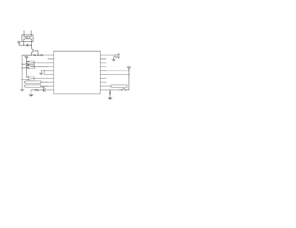
The MS decoder is ideal for replicating button presses for remote control
applications. An example application circuit is shown in Figure 10.
SPDT switches are used to select the baud rate and set the latch mode so
that pull-down resistors are not needed.
The RX_CNTL line can be connected to the PDN line of the receiver or it
can be connected directly to ground.
TX_ID can be connected to a microprocessor or a PC to record the
transmitter identity. Application Note AN-00156 has sample code that
reads the transmitter ID and displays the ID number on a LCD screen.
An LED indicator is attached to the MODE_IND line to provide visual
feedback to the user that an operation is taking place. This line sources a
maximum of 25mA.
The LEARN line is connected to a button that pulls the line high when
pressed. Since the line does not have an internal pull-down resistor, a
100k
Ω resistor is used to pull the line to ground when the button is not
pressed.
The DATA_IN line is connected directly to the data output of the receiver.
To Receiver
2.2k
220
10k
100k
From Receiver
D6
D7
SEL_BAUD0
SEL_BAUD1
GND
GND
LATCH
RX_CNTL
TX_ID
MODE
_IND
D5
D4
D3
D2
VCC
VCC
D1
D0
DATA_IN
LEARN
1
2
3
4
5
6
7
8
9
10
11
12
13
14
15
16
17
18
19
20
LICAL-DEC-MS001
To Processor or PC
Figure 10: MS Series Decoder Application Circuit
Data Lines D0 through D7 can be connected directly to the external
circuitry that needs to be activated remotely. In this example, D5 is
connected directly to a piezoelectric buzzer. This causes the buzzer to
sound when the D5 line on the encoder goes high. Line D6 activates a
relay through a transistor buffer when it goes high. A buffer like this may be
needed if the load requires more than 25mA of current or a higher voltage
source to activate. The decoder turns on the transistor, which can be
selected to provide the appropriate drive levels to activate the relay.