Typical performance graphs – Linx Technologies RXM-xxx-LR User Manual
Page 5
– –
– –
4
5
LR Series Receiver Specifications Continued
Parameter
Symbol
Min.
Typ.
Max.
Units
Notes
Max. Time Between
Transitions
10.0
ms
5
Environmental
Operating Temperature
Range
–40
+70
ºC
5
1. The LR can utilize a 4.3 to 5.2VDC supply provided a 330
Ω resistor is placed in series
with V
CC
.
2. Into a 50
Ω load.
3. When operating from a 5V source, it is important to consider that the output will swing
to well less than 5 volts as a result of the required dropping resistor. Please verify that
the minimum voltage will meet the high threshold requirement of the device to which
data is being sent.
4. For BER of 10
–5
at 1,200bps.
5. Characterized, but not tested.
6. Time to valid data output.
Warning:
This product incorporates numerous static-sensitive
components. Always wear an ESD wrist strap and observe proper ESD
handling procedures when working with this device. Failure to observe
this precaution may result in module damage or failure.
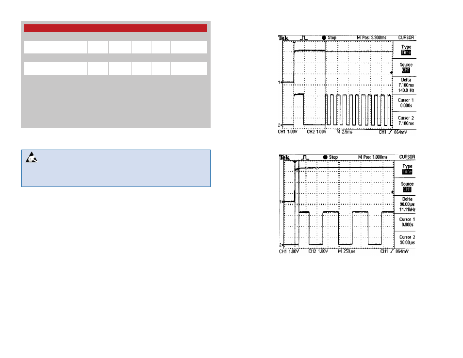
Typical Performance Graphs
Supply
RX Data
RX Data
PDN
Figure 4: Electrical Specifications
Figure 5: Turn-On Time from V
CC
Figure 6: Turn-On Time from PDN