Pin assignments, Pin descriptions, Module description – Linx Technologies TXM-xxx-LR User Manual
Page 6
– –
– –
6
7
Module Description
The LR Series transmitter is a low-cost, high-performance synthesized
ASK / OOK transmitter, capable of sending serial data at up to 10,000bps.
Because the transmitter is completely self-contained, requiring an
antenna as the only additional RF component, application is extremely
straightforward and assembly and testing costs are reduced. The LR
is housed in a compact surface-mount package that integrates easily
into existing designs and is equally friendly to prototyping and volume
production. LR Series modules are capable of meeting the regulatory
requirements of domestic and international applications.
The module’s low power consumption makes it ideal for battery-powered
products. The transmitter is compatible with many other Linx receiver
products, including the LR, KH3, LT and OEM product families. For
applications where range is critical, the LR receiver is the best choice due
to its outstanding sensitivity.
The transmitter is capable of outputting +10dBm into a 50-ohm load. When
combined with an LR Series receiver, a reliable serial link is formed capable
of transferring data over line-of-site distances of up to 1.5 miles (2,500m)
when used with good antennas. Legal regulations in the various countries
will require the transmitter output power to be reduced which will reduce
range. Following the legal output limit for transmitters in the United States,
systems based on the LR Series can achieve ranges of up to 3,000 feet
(1,000m).
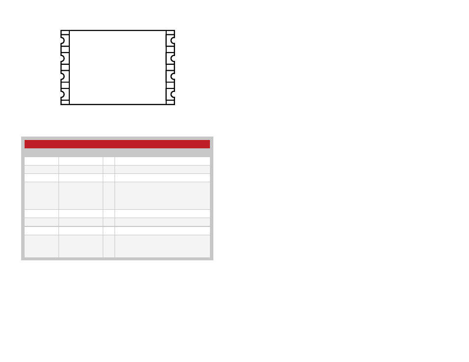
Pin Assignments
GND
DATA
GND
GND
ANT
LADJ/VCC
PDN
VCC
1
2
3
4
5
6
7
8
Pin Descriptions
Pin Descriptions
Pin Number
Name
I/O Description
1
GND
—
Analog Ground
2
DATA
I
Digital Data Input
3
GND
—
Analog Ground
4
LADJ/V
CC
I
Level Adjust. This line can be used to adjust
the output power level of the transmitter.
Connecting to V
CC
gives the highest output,
while placing a resistor to V
lowers the
output level (see Figure 6 on page 4)
5
ANT
—
50
Ω RF Output
6
GND
—
Analog Ground
7
V
CC
—
Supply Voltage
8
PDN
I
Power Down. Pulling this line low places
the transmitter into a low-current state. The
module is not be able to transmit a signal in
this state.
Figure 8: LR Series Transmitter Pinout (Top View)
Figure 9: Pin Descriptions