Universal wall box installation instructions, Flush mount installation – Larco Universal Wall Box User Manual
Page 2
ATEK Access Technologies
10025 Valley View Road, Ste. 190
Eden Prairie, MN 55344 U.S.A.
PH: 1.800.523.6996
FAX: 1.800.589.3705
+1.218.829.9797
www.atekaccess.com
223-0130-000 Rev. D 2/15
Universal Wall Box
Installation Instructions
2
3
4
5
6
7
1
Determine wall switch mounting location based on wall construction,
applicable standards and intended use. In high use and abuse areas, a
solid mounting surface or additional reinforcement may be required
behind the box.
Determine stud location in mounting area. Cut an access hole adjacent to
stud for extra support. Access hole dimensions should be 6-3/4” square
for a full sized (6”) wall switch and 5-1/4” for a reduced size (4-1/4”) wall
switch. Trace around the box as a guide.
Punch out holes in box in areas indicated on the front view drawing by the
notation “mounting screw punch outs” (see reverse side).
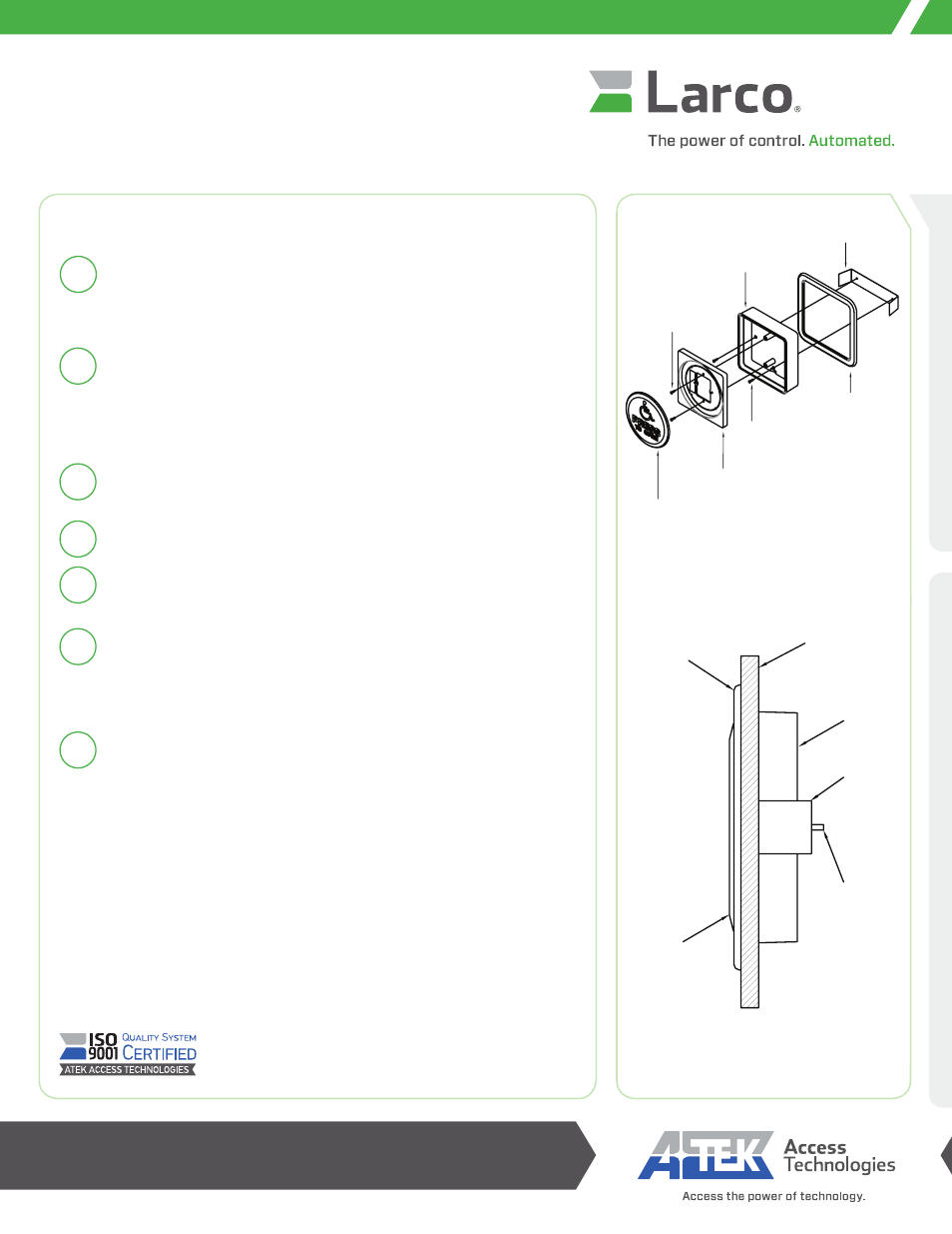
Slide the flush mounting ring over the mounting box.
Thread two #8-32 screws through the pilot holes and into the retaining
bracket. Do not tighten screws completely.
Insert the mounting box and bracket into the access hole. The bracket is
slightly larger than the access hole. Squeeze the sides of the bracket into
the mounting box and gently force the bracket through the hole. Tighten
both screws until the assembly is held tightly to the wall surface.
Complete wall switch assembly using instructions included with the
wall switch.
Flush Mount Installation
Flush Mount Kit Assembly
Flush Mounting
FLUSH
MOUNTING
RING
WALL SWITCH
COVER PLATE
MOUNTING
SURFACE
UNIVERSAL
WALL BOX
FLUSH
MOUNTING
BRACKET
MOUNTING
SCREW
FLUSH MOUNTING BRACKET
ADAPTER PLATE
#6-32 WALL SWITCH
MOUNTING SCREWS
#8-32 MOUNTING SCREWS
WALL SWITCH
UNIVERSAL WALL BOX
FLUSH MOUNTING RING