Chapter 3, Motherboard information – Lanner VES-310 User Manual
Page 12
10
Motherboard Information
Chapter 3
Embedded and Industrial Computing
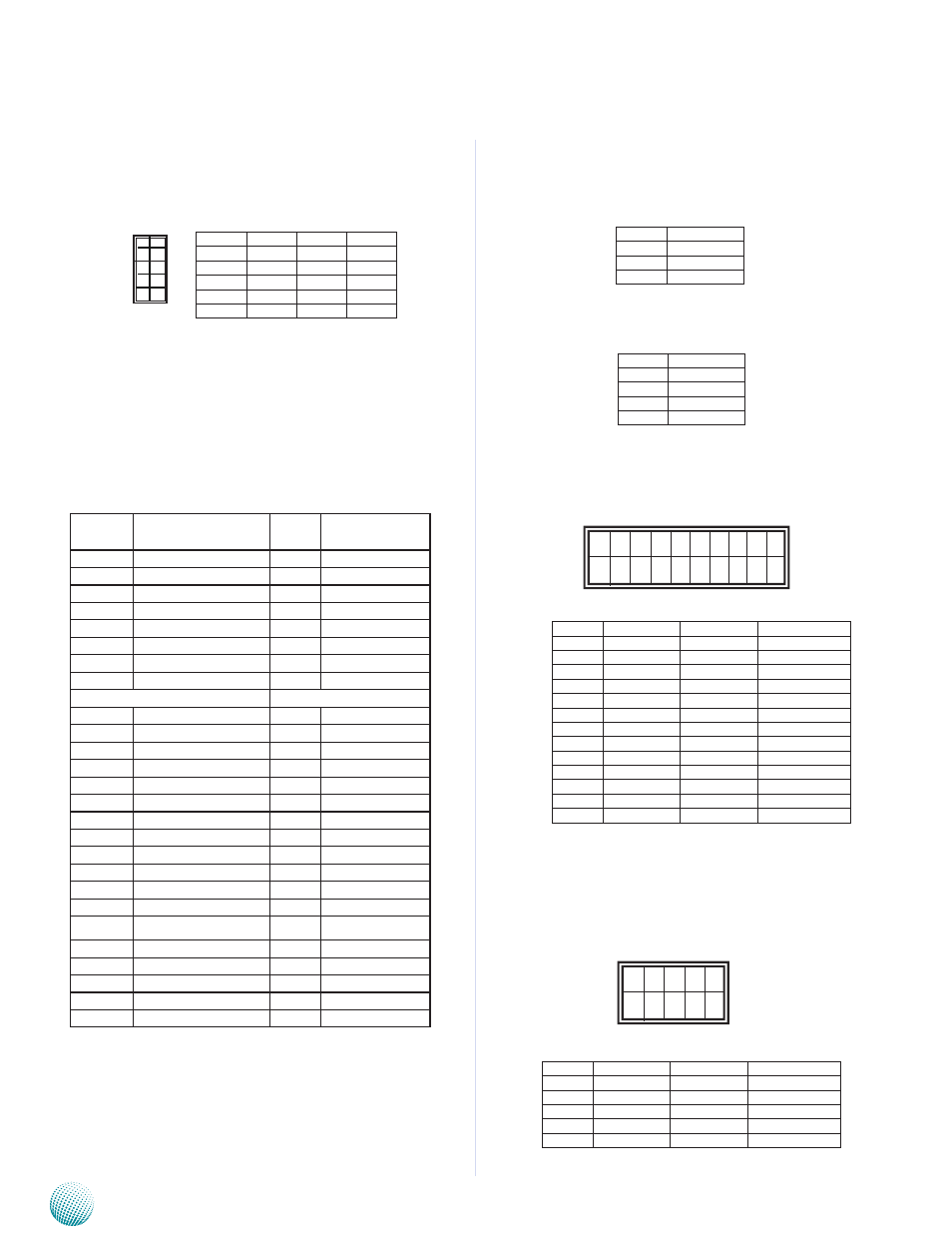
DIO Output Pin (J10): The 8 pins of Digital Input/
Output (DIO) provide connectors for digital input and
output for controlling digital I/O devices.
SO-DIMM Connector (SO-DIMM1): The 200-PIN
DDR2 SO-DIMM connector supports connection of DDR2
667 MHz system memory with a maximum of 2GB.
Mini-PCIe 1X Connector (MPCIE1): It is for
connecting the PCI Express Mini Card such as the wireless
LAN module. The supporting the PCI Express Base
Specification, Revision 1.1.
PIN NO. Description
PIN
NO.
Description
1
WAKE#
2
3.3V
3
RSV1
4
GND
5
RSV2
6
1.5V
7
CLKREQ#
8
UIM_PWR
9
GND
10
UIM_DATA
11
REFCLK-
12
UIM_CLK
13
REFCLK+
14
UIM_RESET
15
GND3
16
UIM_VPP
KEY
KEY
17
RSV3
18
GND
19
RSV4
20
W_EISABLE#
21
GND5
22
PERST#
23
PERn0
24
+3.3Vaux
25
PERp0
26
GND
27
GND
28
+1.5V
29
GND
30
SMB_CLK
31
PETn0
32
SMB_DATA
33
PETp0
34
GND
35
GND
36
USB_D-
37
RSV5
38
USB_D+
39
RSV6
40
GND
41
RSV7
42
LED_WWAN#
43
RSV8
44
LED_WLAN#
45
RSV9
46
LED_WPAN#
47
RSV10
48
+1.5V
49
RSV11
50
GND
51
RSV12
52
+3.3V
Pin No.
Pin Name Pin NO. Pin Name
1
Input1
6
Output3
2
output1
7
Input4
3
Input2
8
Output4
4
Output2
9
GND
5
Input3
10
VCC5
9
7
5
3
1
10
8
6
4
2
12V DC-IN Power Connector (DCJK1): The device
offers two types of power connector which are 12V DC-
in Jack and 4-pin Connector for ATX mode power supply
(listed below).
+12V DC-IN Power Socket for ATX Mode Power
Supply (DCIN1)
Parallel Connector (LPTA1): The parallel connector
is for connecting parallel port interface cable.
Dual USB 2.0 Ports (USBB1): Besides the 2 external
USB type A connectors, the internal pin headers for
connecting USB interface cable for additional 2 USB ports
are also provided.
Pin No.
Pin Name
1
+12V DC-IN
2
GND
3
GND
Pin No.
Pin Name
1
+12V DC-IN
2
GND
3
GND
4
+12V DC-IN
2
26
1
25
Pin No.
Pin Name
PIN NO.
PIN Name
1
Strobe #
2
Auto Form Feed
3
Data0
4
Error #
5
Data1
6
Initialize #
7
Data2
8
Printer Select IN #
9
Data3
10
Ground
11
Data4
12
Ground
13
Data5
14
Ground
15
Data6
16
Ground
17
Data7
18
Ground
19
Acknowledge #
20
Ground
21
Busy
22
Ground
23
Paper Empty
24
Ground
25
Printer Select
26
Key
Pin No.
Pin Name
PIN NO.
PIN Name
1
USB3_VCC
2
Ground
3
Key
4
USBD3+
5
USBD2-
6
USBD3-
7
USBD2+
8
Key
9
Ground
10
USB4_VCC
2
10
1
9