Chapter 3, Board layout, Jumper settings – Lanner LEC-3013 User Manual
Page 15
15
Board Layout
Chapter 3
Embedded and Industrial Computing
Jumper Settings
Serial-ATA Connector (J3): It is for connecting a 2.5’’
harddisk to be served as your system’s storage. It can
support SATA II which features Data transfer rates up to
3.0 Gb/s (300 MB/s).
4-pin Serial-ATA Power Connector (J4): It is for
connecting the SATA power cord.
DC-in Connector (CN1): A DC Power Connector through
Phoenix contact for power input from12~36V.
LAN1/LAN2 (RJ1/RJ2): The LAN ports are provided by
Intel 82574L Ethernet controller whose interface complies
with PCI-e 1.1 (2.5 Ghz). It has advanced management
features including IPMI pass-through via SMBus or NC-SI,
WOL, PXE remote boot, ISCSI boot and VLAN filtering.
Pin No.
Description
Fast Ethernet Gigabit Ethernet
1
TX+
MD0+
2
TX-
MD0-
3
RX+
MD1+
4
T45
MD2+
5
T45
MD2-
6
RX-
MD1-
7
T78
MD3+
8
T78
MD3-
Dual USB 2.0 Port (CN3):
Pin No.
Function
1
GND
2
TX+
3
TX-
4
GND
5
RX-
6
RX+
7
GND
LEB-3013
Pin No.
Function
1
5V
2
Ground
3
Ground
4
12V
7 6 5 4 3 2 1
1 2 3 4
Dual USB Pin Header (USB1):
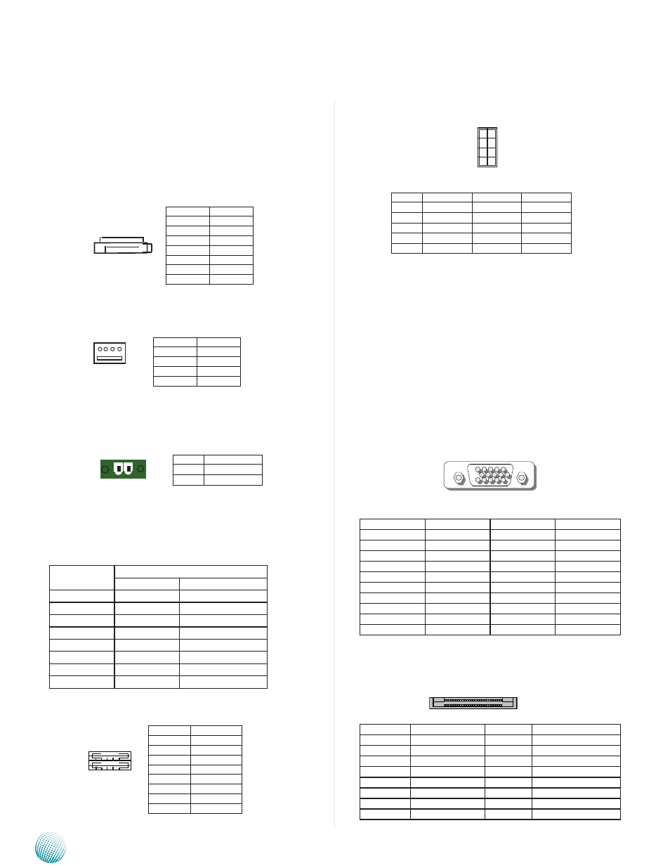
VGA Port (VGA1): It is a 15 pin D-Sub VGA connector. The
VGA is provided by the integrated GPU which implements
Intel® Graphics Media Accelerator 3150 and supports the
following features:
Contains a refresh of the third generation graphics
•
core.
Intel
•
® Dynamic Video Memory Technology support
4.0
Directx* 9 compliant, Pixel Shader* v2.0
•
Intel
•
® Clear Video Technology including MPEG2
Hardware Acceleration and ProcAmp
Pin No.
Description
Pin No.
Description
1
CON_RED
11
NC
2
CON_GREEN
12
CON_DDC_DAT
3
CON_BLUE
13
CON_HSYNC
4
NC
14
CON_VSYNC
5
GND
15
CON_DDC_CLK
6
CRT_ON
7
GND
8
GND
9
VCC5
10
GND
Compact Flash Connector (CN2)
PIN
Description
PIN
Description
1
GND
26
CD1-
2
DATA3
27
DATA11
3
DATA4
28
DATA12
4
DATA5
29
DATA13
5
DATA6
30
DATA14
6
DATA7
31
DATA15
7
CE1#
32
CE2#
8
A10
33
VS1#
Pin No.
Pin Name
1
GND
2
VCC12~36V
1 2
1 2 3 4
5 6 7 8
Pin No.
Pin Name
1
+5V
2
USBD0-
3
USBD0+
4
GND
5
+5V
6
USBD1-
7
USBD1+
8
GND
Pin No. Pin Name
Pin No.
Pin Name
1
USB_VCC
2
Grond
3
Key
4
USBD1+
5
USBD0-
6
USBD1-
7
USBD0+
8
Key
9
Ground
10
USB_VCC
1
3
5
7
9
2
4
6
8
10
1
6
11
5
10
15