Operating instructions – Laney LX35 User Manual
Page 6
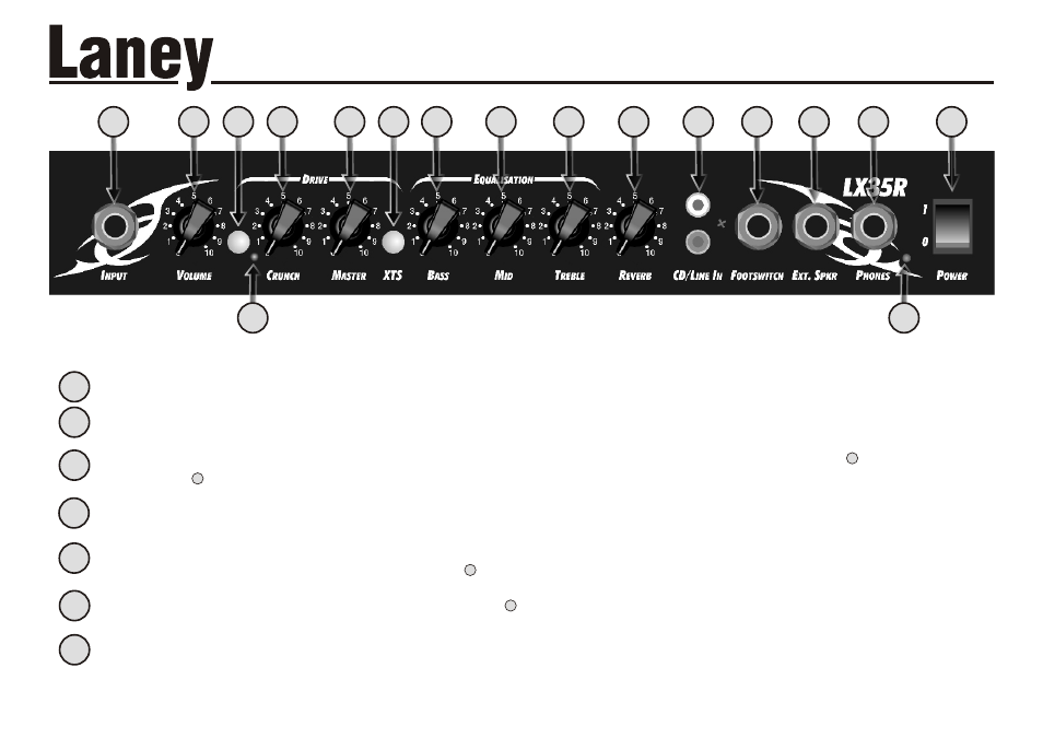
Controls the amount of bass or bottom end present in your sound.
Controls the amount of mid present in you sound.
Controls the amount of treble present in your sound.
Controls the amount of reverb applied to the signal. (LX35R only)
Fancy playing along with a backing track? Connect your CD/MP3 player here.
Connect a Laney FS2 footswitch here to enable remote switching for the channel and reverb/FX. Note: Drive channel must
be enabled for channel switching via footswitch to function.
Fancy playing with the big boys? Connect an external loudspeaker cabinet here. The internal loudspeaker is automatically
disabled. The impedance of the external cabinet must not be less than 4 Ohms. Connecting cabinets that have a lower
impedance than 4 Ohms will result in the amplifier overheating. Continual use in this manner may cause permanent damage.
Don’t want to wake your neighbours? Connect your headphones here. The internal loudspeaker is automatically switched off.
When ‘on’ Indicates that power is connected to the unit and it is ready to go.
(Always switch off and disconnect the power cord when not in use)
Main power switch for the unit.
5
This socket should be used for connecting your instrument to the amplifier. Only use a good quality screened cable.
Controls the volume level of the clean channel.
Switch in to activate the overdrive ‘Crunch’ channel. When active, control the amount of distortion with and the overall
volume with
Indicates that the drive channel is active.
Controls the crunch channel gain, low down for classic rock and blues, higher up for hard rock and metal.... the higher you go
the more Extreme it gets. Use in conjunction with to get the overall level balanced how you want it.
Controls the overall level on the drive channel. Use with
eXtreme Tone Shaping. This applies a scooped mid tone shape to the drive channel and boosts certain key frequencies for a
unique sound.
5
6
6
5
1
Page 6 /12
Page 7 /12
2
3
4
6
7
8
10
11
12
FRONT PANEL CONTROLS
OPERATING INSTRUCTIONS
OPERATING INSTRUCTIONS
1
2
5
6
8
14
17
3
13
4
13
14
7
9
10
11
12
15
16
9
15
16
17