Connections – JBL Synthesis Studio 530 User Manual
Page 7
7
www.jbl.com
E
ng
lis
h
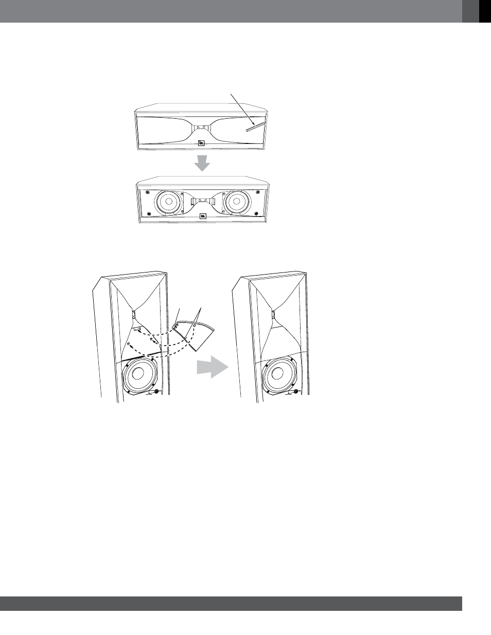
REmoviNG Studio 520C GRiLLES
To remove the Studio 520C grilles, use the provided grille removal tool to pull the grilles away from the enclosure as
shown, then remove them the rest of the way by hand.
Use Tool to Pull Grilles
Away from Cabinet
AttACHiNG tHE HoRN CovERS
If you remove the speakers’ grilles, attach the provided horn covers as shown. Make sure that both rubber bumpers on
the horn cover fit into the holes in the speaker.
Fit Tab
into Slot
Fit
Bumpers
into Holes
COnneCtiOns
CAutioN: make sure that all of the system’s electrical components are turned oFF (and preferably
unplugged from their AC outlets) before making any connections.
Speakers and amplifiers have corresponding positive and negative (“+” and “–”) connectors. All Studio 5 series
speakers have connectors that are marked “+” and “–” on the terminal-cup assembly. Additionally, the “+” connectors
have red markings, while the “–” connectors have black markings.
To ensure proper polarity, connect each “+” connector on the back of the amplifier or receiver to the respective “+”
(red) connector on each speaker. Connect the “–” connectors in a similar way. Do not reverse polarities (i.e., “+” to “–”
or “–” to “+”) when making connections. Doing so will cause poor stereo imaging and diminished bass performance.
impoRtANt: make sure the “+” and “–” wires or connectors do not touch each other or the other terminal.
touching wires can cause a short circuit that can damage your receiver or amplifier.