Application example, Implementation – Yaskawa AC Drive-A1000 User Manual
Page 12
3 Application Selection
12
YASKAWA TM.A1000SW.029 Traverse Application A1000 Custom Software Supplement
Application Example
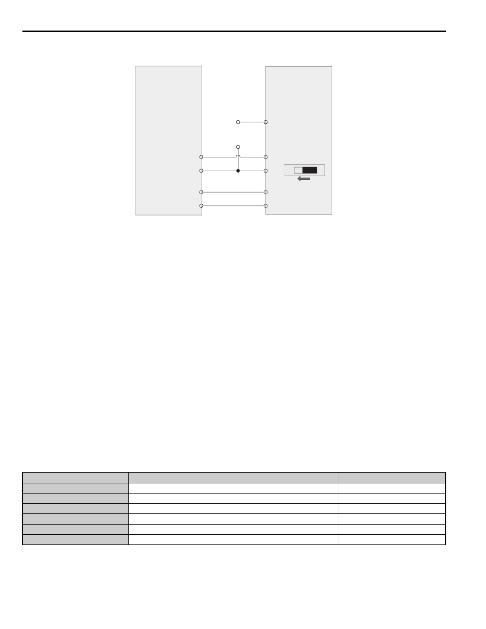
Figure 1
Figure 1 Software and Hardware Configuration for A1000 Traverse
Master Parameter Changes
• H2-01 = 41h: Provide during disturb status output to slave.
• H4-01 = 703: Provide disturbed frequency ripple to slave.
• H4-07 = 1: Provide a bipolar analog output signal.
• P1-01 = 1: Enable Traverse functionality.
• P1-02 ~ P1-05 = application requirements: Define the characteristics of the disturbed frequency.
• P1-06 = application requirement: Define scan offset to account for system delays.
Slave Parameter Changes
• C1-03 = 0.0 sec: Set acceleration time 2 to 0.0 seconds.
• C1-04 = 0.0 sec: Set deceleration time 2 to 0.0 seconds.
• H1-08 = 7: Switch between accel/decel time 1/2 based on During Disturb output.
• P1-01 = 1: Enable Traverse functionality.
• DIP Switch S1 = V: Enable voltage input to A2.
• H3-09 = 1: Set A2 to a -10V to +10V bipolar input.
Implementation
Situation 1: Standard Operation
When programmed with the settings as shown in
, the Traverse software produces output waveforms similar to
the ones in
. Using these settings and a reference frequency of 45 Hz, the master drive operates based on the
triangle waveform with 9 Hz (peak-peak) amplitude. Because the waveform is centered on the 45 Hz reference frequency,
the master waveform oscillates between 36 and 54 Hz while in Traverse mode.
Table 10 Sample Operating Parameters
Parameter
Name
Setting
P1-01
Disturbed Waveform Selection
1
P1-02
Disturbed Waveform Amplitude
20.0%
P1-03
Disturbed Waveform Jump
50.0%
P1-04
Negative Slope Time
5.0 s
P1-05
Positive Slope Time
4.0 s
P1-06
Slave Scan Offset
0 ms
A 1000 (Master)
Traverse Software
MA
MC
A1000 (Slave)
Standard Software
S8
SC
A2
AC
FM
AC
DIP Switch S1
V
I
A1
+
-
Slave
Frequency
Reference
H3-09 = 1
H1-08 = 7
H4-01 = 703
H2-01 = 41