Page 5 of 5 – Yaskawa iQpump1000 AC Drive User Manual
Page 5
Step
9
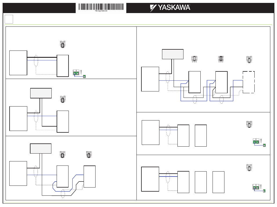
Transducer Connections
Page 5 of 5
Yaskawa America, Inc., 2121 Norman Drive South, Waukegan, IL 60085, (800) YASKAWA (927-5292) Fax (847) 887-7310, [email protected], www.yaskawa.com, Document Number: TM.iQp1000.03 05/29/2014 © Yaskawa America, Inc.
Output
4-20mA
Transducer
V+
A2
AC
+24V
EG
iQpump1000
Set Jumper S1-2 to ‘I’ Position (4-20mA) for
iQpump1000 Drive (Factory Default).
Output
4-20mA
Outlet
Transducer
V+
AC
A2
EG
A2
AC
EG
iQpump1000 - 1
iQpump1000 - 2
+ -
External
24Vdc Power Supply
Set jumper S1-2 to ‘I’
Position (4-20mA) for
both iQpump Drives
(Factory Default).
Output
Set jumper S1-2 to ‘I’ Position for the last iQpump1000
Drive on the network. All other iQpump1000 drives
should have S1-2 set to ‘V’.
Last drive on
the network
4-20mA
Transducer
V+
A2
AC
EG
AC
A2
EG
A2
AC
+V
EG
+ -
External
24Vdc Power Supply
External Power
Supply only required
when connecting 2 or
more drives.
Output
Last drive on
the network
4-20mA
Transducer
V+
A2
AC
EG
AC
A2
EG
A2
AC
+V
EG
iQpump1000 - 1
iQpump1000 - 2
iQpump1000 - 3
(Factory Default)
A1 A3
A2
V
I
Simplex System – Single Transducer Connection using Analog Input A2
Duplex System: Single Transducer Connection using Analog Input A2
(External Power Supply)
(Factory Default)
A1 A3
A2
V
I
(Factory Default)
A1 A3
A2
V
I
iQpump1000 - 1
iQpump1000 - 2
iQpump1000 - x
(Factory Default)
A1 A3
A2
V
I
A1 A3
A2
V
I
A1 A3
A2
V
I
Triplex System: Single Transducer Connection using Analog Input A2
(External Power Supply)
Duplex System: Single Transducer Connection using Analog Input A2
S1
S1
S1
S1
S1
S1
2-Wire Transducer
2-Wire Transducer
2-Wire Transducer
2-Wire Transducer
Jumper located
inside the drive on
the terminal board
Jumper located
inside the drive on
the terminal board
Jumper located
inside the drive on
the terminal board
Jumper located
inside the drive on
the terminal board
*
*
*
*
*
*
*
*
*
*
Output
4-20mA
Transducer
V+
A2
AC
+V
EG
iQpump1000
+ -
External
24Vdc Power Supply
Set Jumper S1-2 to ‘I’ Position (4-20mA) for
iQpump1000 Drive (Factory Default).
(Factory Default)
A1 A3
A2
V
I
Simplex System – Single Transducer Connection using Analog Input A2
(External Power Supply)
S1
2-Wire Transducer
Jumper located
inside the drive on
the terminal board
*
*
AC 24V
SN
Factory
Installed
Jumper
AC 24V
SN
Factory
Installed
Jumper
P9-02 = 3
P9-02 = 3
P9-02 = 2
Output
Last drive on
the network
4-20mA
Transducer
V+
AC
A2
EG
A2
AC
+V
EG
iQpump1000 - 1
iQpump1000 - 2
P9-02 = 3
P9-02 = 2
Set P9-02 Feedback Source to ‘2’ for iQpump1000 #1
and to 3 ‘Network’ for iQpump1000 #2.
Triplex System: Single Transducer Connection using Analog Input A2
Set P9-02 Feedback Source to ‘2’ for iQpump1000 #1
and to 3 ‘Network’ for iQpump1000 #2 and #3.
AC 24V
SN
Factory
Installed
Jumper
(Factory Default)
A1 A3
A2
V
I
S1*
(Factory Default)
A1 A3
A2
V
I
S1*
Set Jumper S1-2 to ‘I’
Position (4-20mA) for
iQpump1000 Drive #1
(Factory Default).
Set Jumper S1-2 to ‘I’
Position (4-20mA) for
iQpump1000 Drive #1
(Factory Default).
*
*
iQpump1000 AC Drive
Multiplex Quick Start Procedure