Yaskawa V7 Large HP User Manual
Page 3
Date: 07/01/04, Rev: 04-07
Page 3 of 5
TM.V7SW.032H
Additional Parameters:
No.
Memobus
No.
Parameter Description
Unit
Setting Range
Defaul
t
Access Level
Change
During
Run
n045
012DH
Ratio Numerator
-
1 ~ 9999
1
First function
Y
n046 012EH Ratio
Denominator
-
1 ~ 9999
1
First function
Y
n170
01AAH
PID Dancer Setpoint
Hz*
0.00 ~ 400.0Hz**
0.00
Fourth Function
Y
* Unit depends on the setting of parameter n035 (Display Unit of Frequency Reference).
** For settings greater than 99.99, only one decimal place will be displayed.
Parameters n045 and n046 apply a ratio to the winder frequency reference. By setting n170 to a nonzero
value, it becomes the PID setpoint.
Additional Reference Selection Setting:
Setting Description
10
Winder ratio reference
When n004 = 10, the inverter frequency reference will be given by the winder ratio reference.
Additional Memobus Register:
Memobus
No.
Parameter Description
Unit
0004H
Winder frequency reference
1 = 0.01Hz
This register is only accessible using a Memobus broadcast command (slave address 0), so no response
message will be sent to the master. Any word length data is considered valid data; if the post-ratio
reference is greater than n011 (max frequency), the commanded reference will be n011 (See Fig. 2).
Detailed Description of Functionality:
Ratio Function
When n004 = 10, the frequency reference is given by the Memobus broadcast register 0004H multiplied
by the ratio of n045 / n046.
n046
n045
0004H
register
Memobus
reference
Frequency
×
=
The calculation is updated each time a write to the register is made.
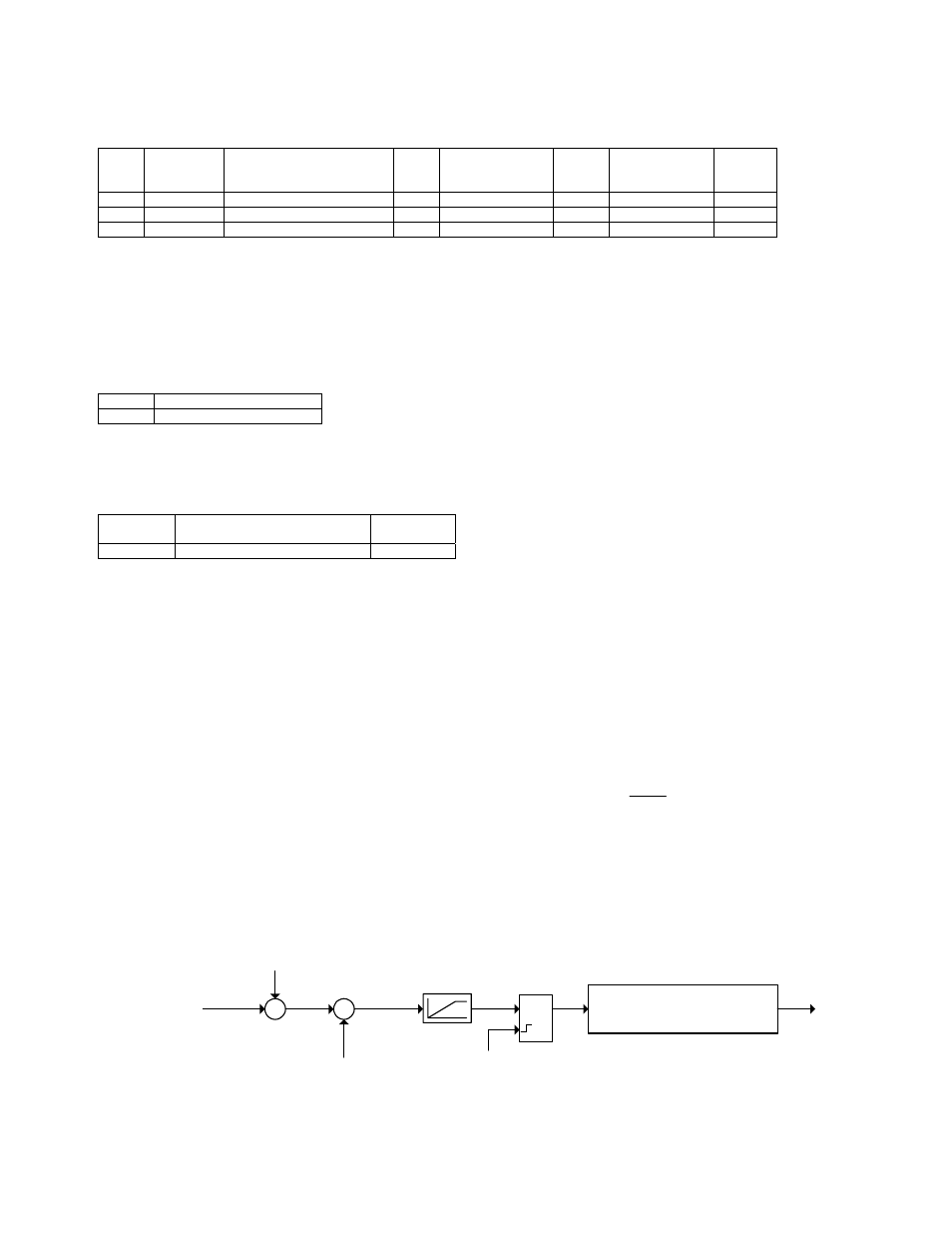
Fig. 2 – Block Diagram of Winder Ratio Frequency Reference
x
n040
Ratio Numerator
÷
n041
Ratio Denominator
Memobus broadcast
register 0004H
n011
Max Frequency
Frequency
reference
Upper/lower limit (n033/n034)
Jump frequencies (n083 - n085)
Minimum frequency (n016)
New write
to 0004H