Yaskawa V7 Decel Positioning User Manual
Page 3
Date: 12/02/04, Rev: 04-12
Page 3 of 6
TM.V7SW.030
2. Overview
This software is intended for simple positioning applications using limit switches. The software modifies the deceleration
time based on the speed reference so that the creep distance (and therefore the cycle time) is minimized.
3. Related Parameters and Functions
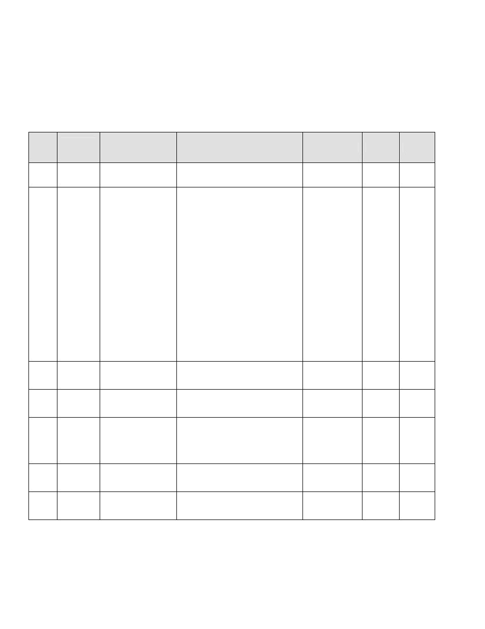
3.1 Parameters
No.
Modbus
Address
Parameter Name
Description
Range
Unit
Default
P-01 0580H
Decel Positioning
Function Selection
0: Decel positioning is disabled.
1: Decel positioning is enabled.
0 ~ 1
-
0
P-02 0581H
Position Speed
Operation Mode
Selection
0: Position speed mode is
disabled. When the drive is
stopped it calculates the
correct decel time based on
the current output frequency.
1: Position speed mode is
enabled. When the position
speed select multi-function
input is closed, the drive
decelerates to position speed
(P-04), using its calculated
decel time. When the run
command is removed, it stops
using its normal decel time.
2: Decel Positioning is enabled –
during Ink Dip decel time is
n022 setting.
0 ~ 2
-
0
P-03
0582H
Decel Time Limit
Sets the upper limit of the
deceleration time during decel
positioning.
0 ~ 300.0
0.1sec
300.0
P-04 0583H Position
Speed
Sets the creep speed for position
speed mode.
0 ~ 400.0
0.01Hz*
2.00
P-05 0584H
Decel
Compensation
Gain
Applies a gain to the calculated
decel rate when the output
frequency at stopping is less than
the decel compensation
frequency (P-06).
1.00 ~ 2.00
-
1.00
P-06 0585H
Decel
Compensation
Frequency
Sets the frequency below which
the decel compensation gain is
applied.
0.01 ~ 400.0
0.01Hz*
50.00
P-07 0586H Ink
Dip
Reference
Sets the frequency reference
used during Ink Dip.
0 ~ 400.0
0.01Hz*
2.00
*For settings greater than 99.99 Hz, the unit is 0.1 Hz.
Note: P-01 ~ P-07 appear after n039 in the programming menu.