Yaskawa Microtrac Gateway to Square D Sy/MAX Family of PLCs for use with Microtrac LAN User Manual
Page 7
7
4/12/94
4
OPERATION
Logic (I/O) Data
The subchannel number will also be in decimal, and will directly correspond to
the bit number of the PLC input. Thus, the 16 possible bits are as follows:
Subchannel 1 = Bit 1
Subchannel 2 = Bit 2
Subchannel 15 = Bit 15
Subchannel 16 = Bit 16
Only one drive can send a logic output (LOGO) to a particular register and bit
of the PLC input function. If more than one drive attempts to initialize the
same bit (subchannel) in a given register, a “Logic Output Allocation Error”
message will be sent to the drive over the ARCNET LAN.
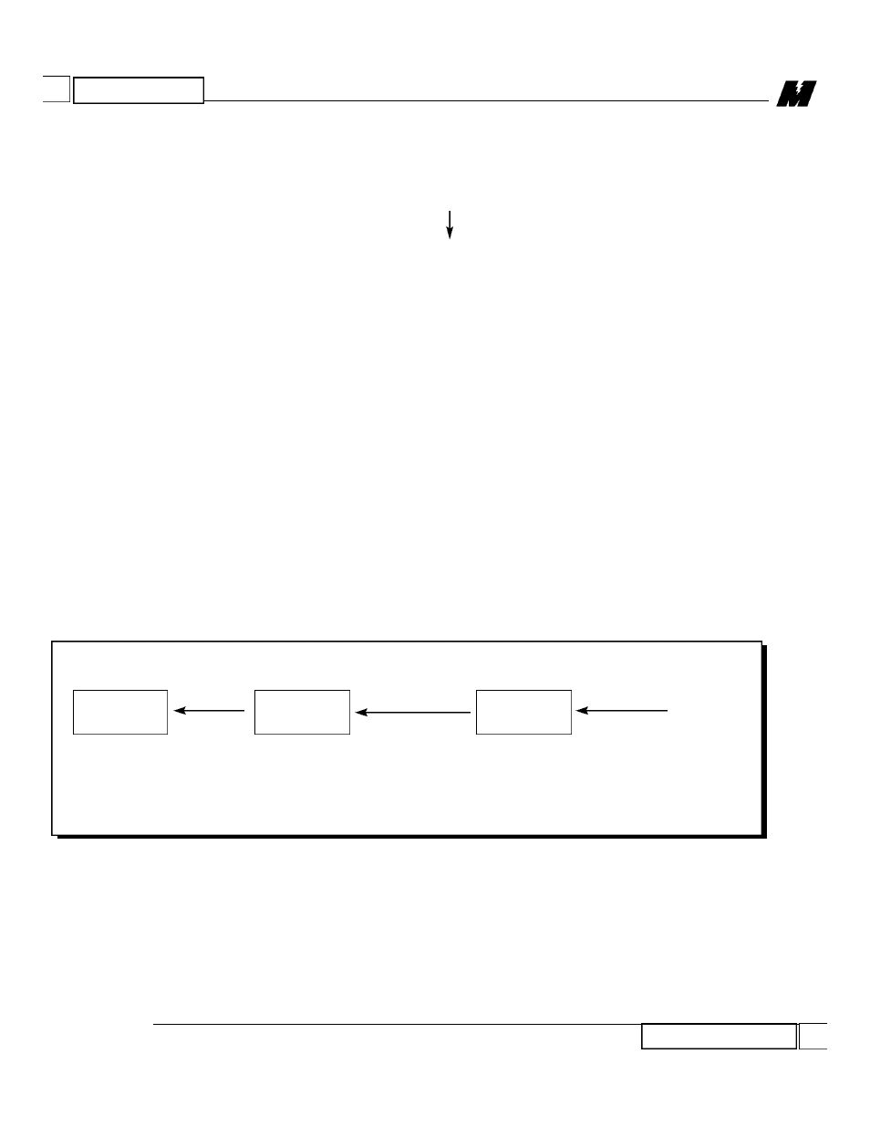
Logic Inputs (LOGI) to a PAC schematic from a PLC is illustrated in
Figure 2.
Each PAC block requires a node number, a channel number, and a subchannel
number.
The node number will usually be 200.
The channel number will be in decimal notation. The associated interfaced
PLC register is the PAC channel number plus 3500. For example:
Channel 11 = PLC Gateway Register 11 = PLC Register 3511
Channel 123 = PLC Gateway Register 123 = PLC Register 3623
Figure 2.
PLC to PAC Logic Input
PAC BLOCK
PLC GATEWAY
PLC LADDER LOGIC
LOGI
WRITE
ARCNET
CABLE
SY/LINK
COMM
CABLE
3511
---
I I
---
-02
NODE: 200
CHAN: 11
SUB:
2
ROUTE: 10
REGISTER: 11
BIT: 2
ROUTE: 110
REGISTER: 3511
BIT: 2
RD 914-10